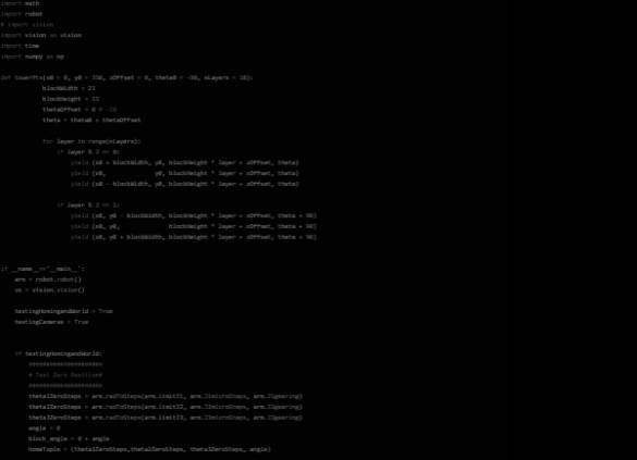
This robotic arm is practically useless without the software and firmware to control it! We modeled a control scheme like that of industrial robot arms where there is a dedicated robot controller taking care of the arm’s movements and a different computer and piece of software telling the arm what to actually do. To accomplish our goal of stacking jenga blocks we also utilized OpenCV to accomplish various vision related tasks like locating the jenga blocks within the world!
The software behind this project is broken into four main chunks:
A frame is captured from the overhead camera each time the robot completes a block placement. We use OpenCV, a popular computer vision package for Python, to orient the frame relative to the baseboard, and to detect block locations in world coordinates for our robot to pick up. Because we have a clean black background, we can perform basic color masking to detect blocks with a high degree of accuracy. We use OpenCV to detect the corner locations, derive the center point and angle of rotation, and pass it on to the inverse kinematics algorithm.
Some limitations of our simple color masking approach are that it is difficult to detect individual blocks when they are clustered together, or when they are partially obscured by, e.g., the robot arm if it is in the frame. It can also cause false detection, particularly near the edges of the baseboard. To remedy this, we identified strict bounding sizes, and we filtered for rectangles with the exact dimensions of a Jenga block.
Another technique we explored was erosion and dilation of the image prior to color masking. This was remarkably effective at distinguishing individual blocks in clusters; however, it also shifted the center of the block in an unreliable way. Lasly, we also captured binary images of regions where we manually classified the presence of blocks. Using a semiautomated workflow, we classified over 1,500 images; these could be fed into a machine learning algorithm to more accurately identify blocks, even when in clusters or partially obscured.
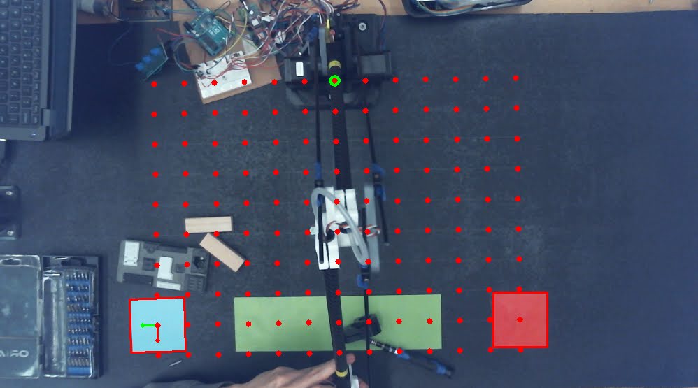
Our basis calculations that are used to map pixel coordinates to world coordinates went through several iterations. We started by having multiple colored squares in known positions on the board, and we detected them with similar color-masking techniques to what we used for detecting blocks. We knew the locations of the center of these squares and used those points to determine the rotation and position of the board within the camera frame. This information is combined into basis vectors that we can use to convert between pixel coordinates and world coordinates. The picture with a red grid shows how the 2 tags were detected and then used to determine basis vectors that then are used to create the red dot grid that is world coordinates spaced 50mm apart.
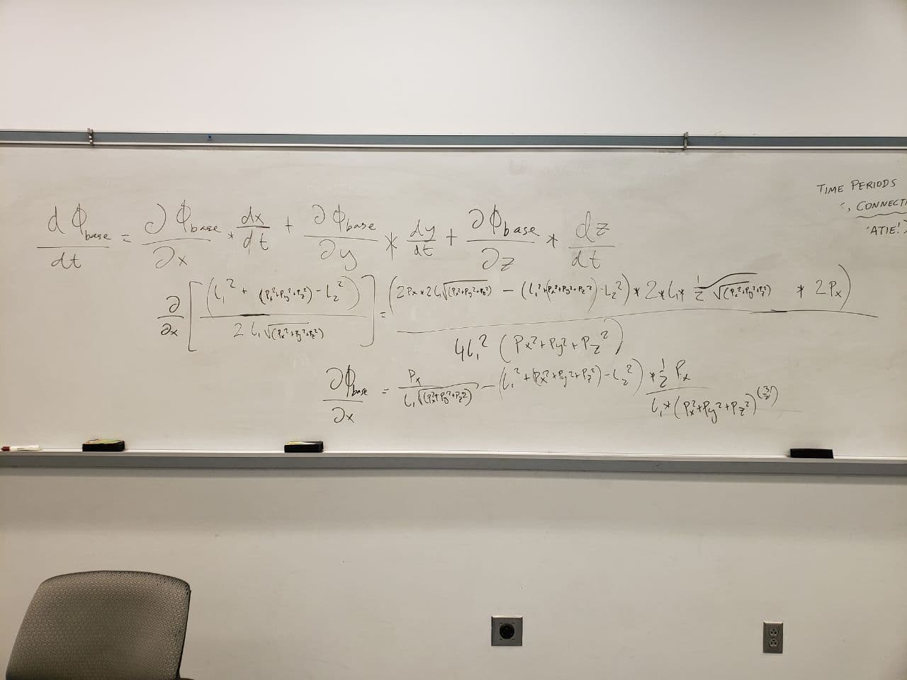
For our purposes it is essential to establish a mapping of the robot into the world space! These are called the inverse kinematics. In industrial applications inverse kinematics allow for the smooth movement of robots along any vector. This is accomplished by mapping the partial derivatives of cartesian space into partial derivatives of each joint.
Fortunately for us the forward kinematics of this arm are quite simple and just involve decomposing the various angles into x,y, and z components.
The inverse kinematics, or figuring out how to position the robot to reach a point in space is a little more difficult! We have a 4 axis system, which actually allows us to reach each position in a variety of positions. This design was intentional because we want to be able to be able to have different end effector rotations to pick up the blocks for stacking.
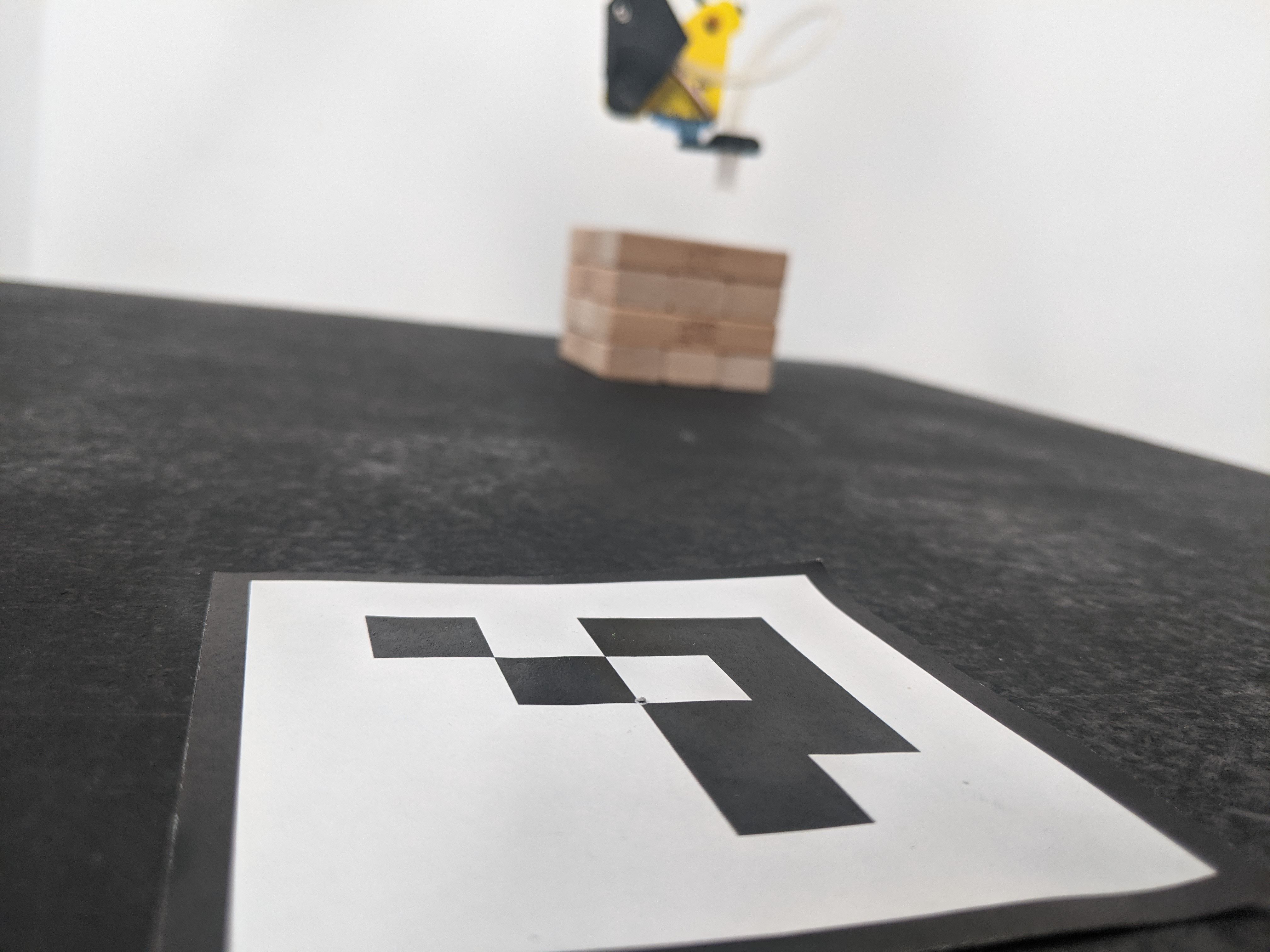
The way we constrain these solutions is picking up the block in a reliable manner. We chose to always have the final joint rotated normal to a block as that gives us the ability to place it. This means that for any point in space we also specify the rotation of the block at that point. You can see an example of this below.
We then work backwards from this point to calculate the rest of the arm. We know the rotation of the final joint and block, which means we can decompose it’s X and Y coordinates. We also know the height of the suction cup and servo which allows us to work backwards from in the Z coordinate direction. We have now calculated the desired position of the servo horn. We know that it is in the same plane as our arm so we can determine the bottom joint angle needed to get to that position. We can then subtract out the offset from the servo horn to the final pivot point in the arm linkages!
At this point we just need to solve a triangle to get the two angles of the arms(j2 and j3). This can be done using the law of cosines since all side lengths are known! The triangle angles are then converted to the angles of the arms! Tada! -- we just converted cartesian coordinates to joint positions that the robot can understand.
So it turns out that this was wildly successful for a first attempt at this problem, however we were starting to get limited by some things. The mechanical design of the robot was making it hard to tell if the round tubes were lined up and other weird rotation/offsets were introduced. We had a hard time picking up blocks from the center. This was largely due to mapping the joints of the robot into the world frame. We think this was caused by errors in the mechanical design but also in our inability to accurately measure the groundtruth positions during homing.
In the future we think adding encoders, and other measurement devices to the arm would allow us to get greater position and more accurate positioning. We also want to represent our kinematics in matrix form such that it is easier to obtain smooth motion by looking at derivatives along axes. This would enable many more use cases for our robot but would necessitate precise closed loop speed control.
From a software side, we are starting to get a little slow, it would be awesome to take this up a level and run ROS2 on a Raspberry Pi and See if we can run things fast enough to maintain closed loop control of the motors and message between things. Our control scheme is very linear right now, but with ROS it would be awesome and possible to do vision processing at the same time as robot movement/calculations!