Electrical System
We designed the electrical system to integrate as easily with the software systems as possible. Thus, everything was accessible under an easy to use Python “driver” interface as described in the Software portion of the website. In addition, we made the final design found in Sprint 3 as tightly integrated with the Mechanical system after a near tragic accident during Sprint 2.
Power Delivery
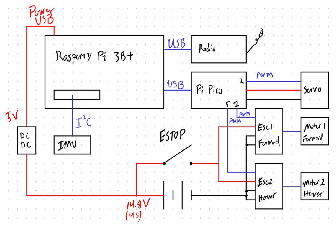
We powered the hovercraft with a 4S LiPo battery, although it can take anything between a 3S and a 5S. We used a DC DC Buck converter to step down the voltage to 5V. This was used to power the Raspberry Pi over USB, which was used to power everything else. The only components operated directly from the battery’s voltage were the ESCs.
Computer
The electrical system is the designed around a Raspberry Pi 3B+ (upgraded from Sprint 1’s Pi 2) and a Raspberry Pi Pico microcontroller. The two communicate over USB. Using a microcontroller in addition to a single board computer has the following advantages:
- The Raspberry Pi 3B+ technically has 4 PWM pins but only 2 PWM channels. Thus, we can only generate 2 of the 3 PWM signals we required for motor control. In addition, the PWM generation on the Pi is unreliable.
- It improves software performance. The Pico handling the motor control frees up CPU time to run more sophisticated controllers.
Motors
The motors and ESCs were chosen in collaboration with the mechanical team. We settled for an EMAX ECO II Series 2207 2400Kv Motor, a part typically used for drones. This would provide more than enough power. We picked ESCs that would suffice to drive the motor with a 4S battery, ultimately picking the RDQ 3-6S BLHeli_S DShot600 30A ESC.
The ESCs receive power directly from the battery. In case we lose control from the software or microcontroller, we built in a physical ESTOP switch that cuts power from the ESCs.
Servo
We controlled the rudder with a hobby servo servo. This was powered the Pico’s VBUS (5V) connector. It was controlled via a 3.3V PWM signal.
Peripherals
We connected peripherals to the GPIO pins on the Raspberry Pi. We used a 9-Axis
IMU from Adafruit. This communicated
to the Raspberry Pi through I²C and the CorrectedIMU class on the software
side.
We purchased a GPS/GLONASS unit from Adafruit as well. This would have talked to the Raspberry Pi over UART. Unfortunately, we never got to integrating the GPS.
Radio
Lastly, we purchased a set of cheap USB LoRa module from Amazon. We would have attached one unit to the Raspberry Pi and the other unit to a laptop running a user interface. Unfortunately, one of the units fried itself. The lesson we learned was to never cheap out on your electronics.