CAD Files
Click here to download the CAD files for our project.
Summary
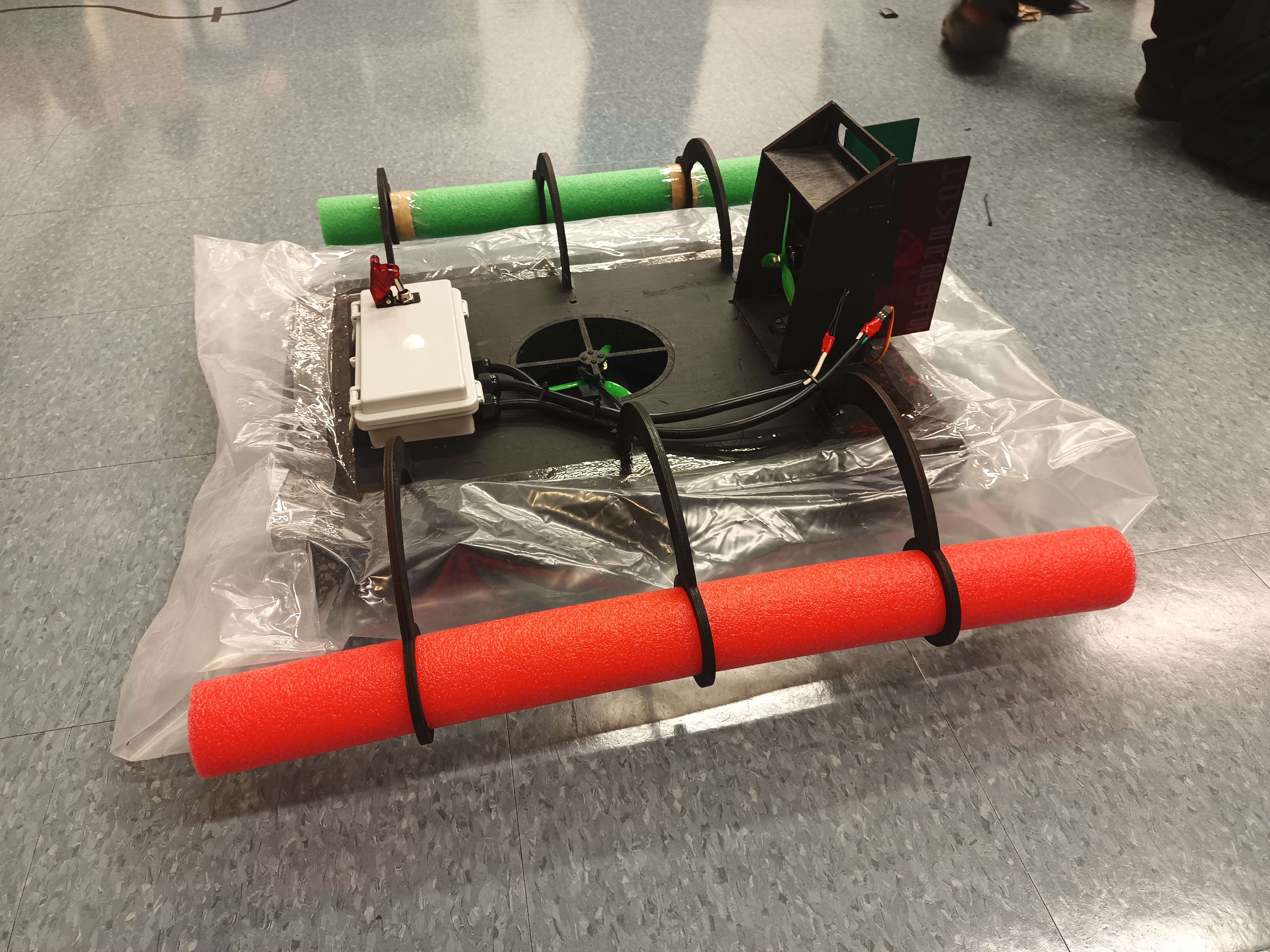
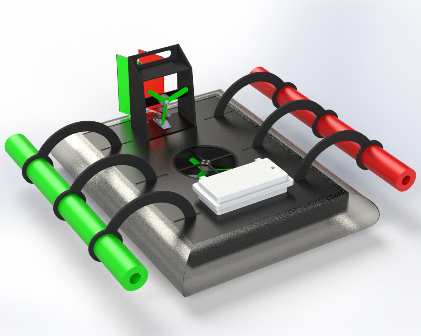
Every aspect of the mechanical design of the Waterstrider is centered around the principles of light weight, water resilience, and flotation. The main chassis is CNC machined from a block of foam to be light and give positive flotation in the case of a loss of power on the water. The lift motor is mounted in a duct in the center of the chassis via a plywood plate and 3mm machine screws. The thrust motor and rudders are mounted to a plywood superstructure at the stern of the hovercraft. As a safety measure against capsizing, auxiliary outriggers are mounted on the port and starboard sides of the Waterstrider via plywood legs. These outriggers do not touch the surface of the water in normal operation, but instead will only make contact with the water when the heel angle exceeds safe margins. All electronics except for the motors are housed in a waterproof enclosure mounted into the forward deck of the hovercraft to keep sensitive systems safe from the aquatic environment.
Risk Identification and Management
We identified the major mechanical risks of this project as:
- Ability to hover
- Sinking
- Capsizing
- Water Shorting Electronics
To mitigate these risks, we made design decisions at every level, including the following high level design choices:
- Use closed plenum hover design
- Introduce positive flotation in structural elements
- Utilize outriggers as safety measure
- Utilize waterproof electronics enclosure
Detailed Design
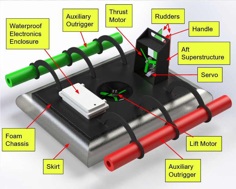
The mechanical design of the Waterstrider is composed of the following subsystems:
- Chassis
- Hover System
- Aft Superstructure
- Outriggers
- Waterproof Electronics Enclosure
Chassis
The foam chassis is the core of the design of the Waterstrider. We designed the chassis is designed to be CNC machined from a single piece of 2" thick foam, which creates a light, positively buoyant, structure. All above-deck mechanical subsystems are mounted into wells in the foam for robust, positive retainment. The below-deck air system is bonded to the bottom of the foam with flexible, fast-setting glue. The skirt is bonded to the chassis with clear tape.
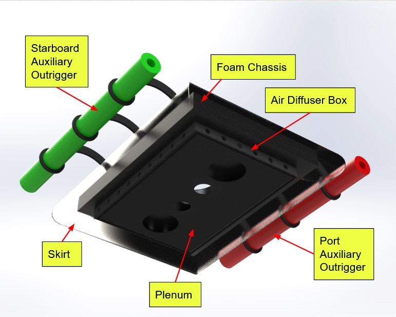
Hover System
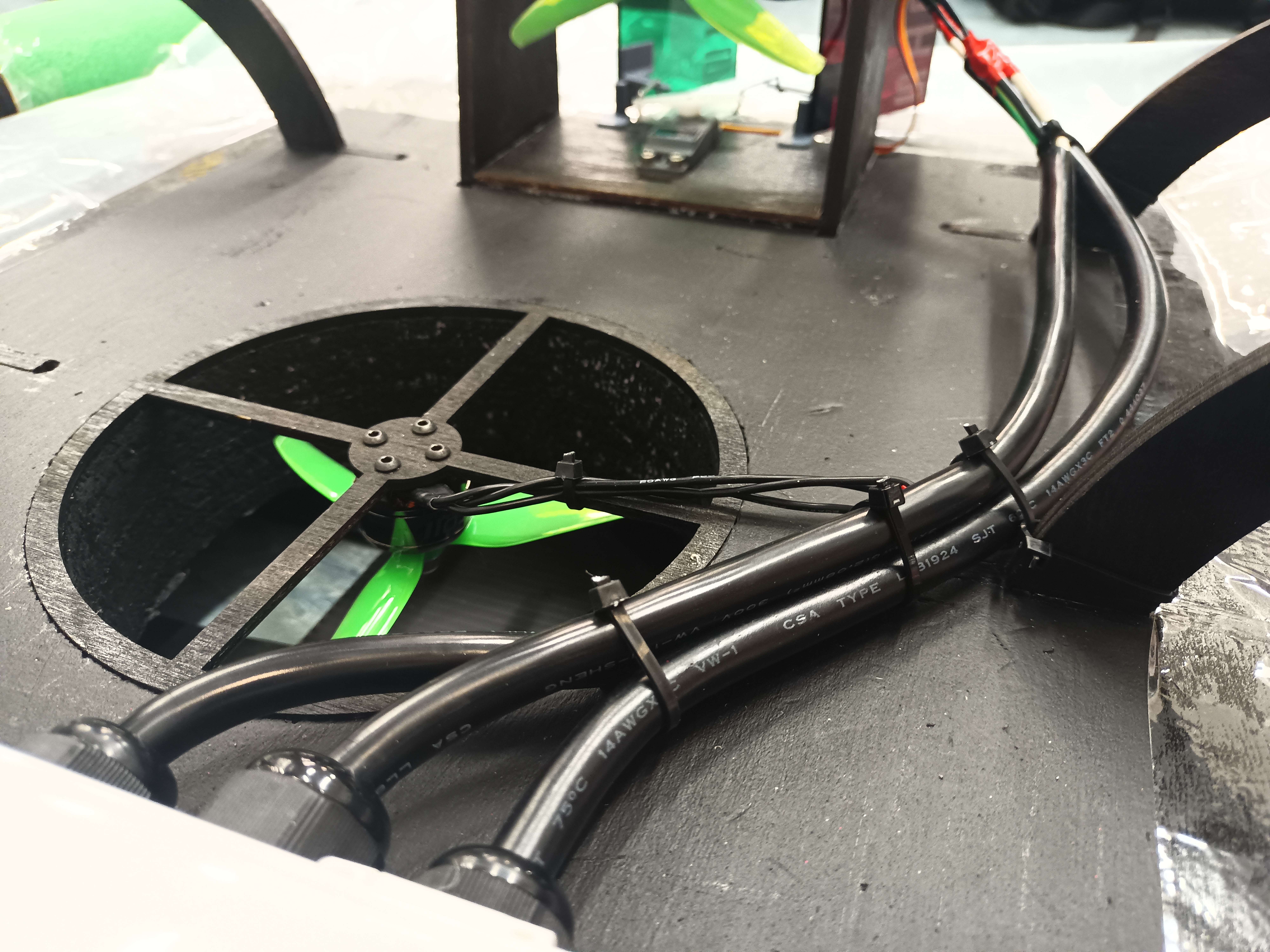
For maximum hover performance, the Waterstrider utilizes a closed plenum design with a compliant skirt. The closed plenum design increases the hover performance for significantly less power draw compared to an open plenum design due to the momentum curtain theory, and the compliant skirt maintains the cushion of air over irregular surfaces like grass and gravel. The source of air movement is a lift fan mounted in a duct in the chassis.
In a closed plenum hovercraft, air is directed downward through the lift fan and hits the plenum, which redirects the air sideways to inflate the skirt. The air can only exit the plenum via the skirt and through carefully located relief holes in the edges of the plenum. To achieve this, we created a box with plywood sides and a CoroPlast bottom. The top of the box is bonded to the bottom of the foam chassis, and the bottom of the box acts as the plenum. Holes in the sides of this box allow air to inflate the skirt, and carefully located holes in the plenum ensure that escaping air is directed inside the momentum curtain.
The skirt is made from a mattress bag. This choice of material is light, waterproof, durable, and flexible. The lift motor is mounted into the duct via an eight inch plywood plate that is bonded into a shallow well in the plywood chassis. The motor is attached to the plywood with 3mm machine screws for easy removal and swapping.
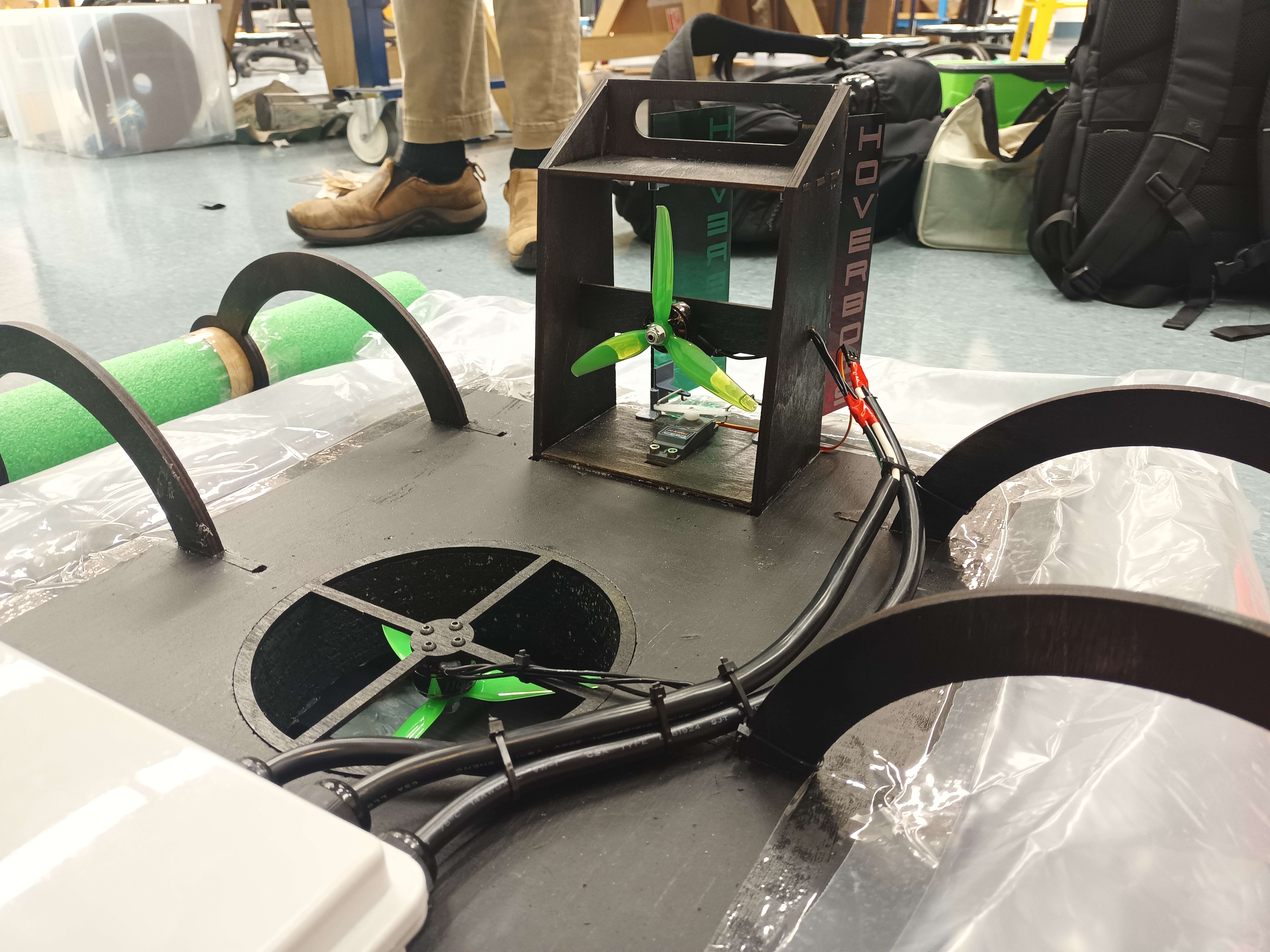
Aft Superstructure
The rudders, rudder servo, thrust motor, and handle are all mounted to a single integrated aft superstructure. The superstructure is made of a combination of eighth inch and quarter inch plywood. The sides of the superstructure are mounted into 1" deep slots in the foam chassis, which creates the equivalent of a Mortise-Tenon joint between the foam and the plywood for high strength. This also means that loads applied to the aft superstructure are transferred to the foam chassis over a larger area to prevent brittle fracture of the foam due to point loading. The thickness of these side panels was chosen as quarter inch instead of eighth inch for increase structural strength of this load-transferring component, and to accommodate machining the foam with larger tooling.
The rudder servo mounts to a plate in the bottom of the superstructure via four #6 machine screws, and the servo is also bonded to a well in the foam chassis for retainment from both structures. The servo controls the rudders via a linkage system. The linkage system for each rudder consists of a 3D printed control horn, the servo horn, and a steel push-rod. These elements form a 4-bar linkage with one degree of freedom that rotates the rudder based on the angular position of the servo.
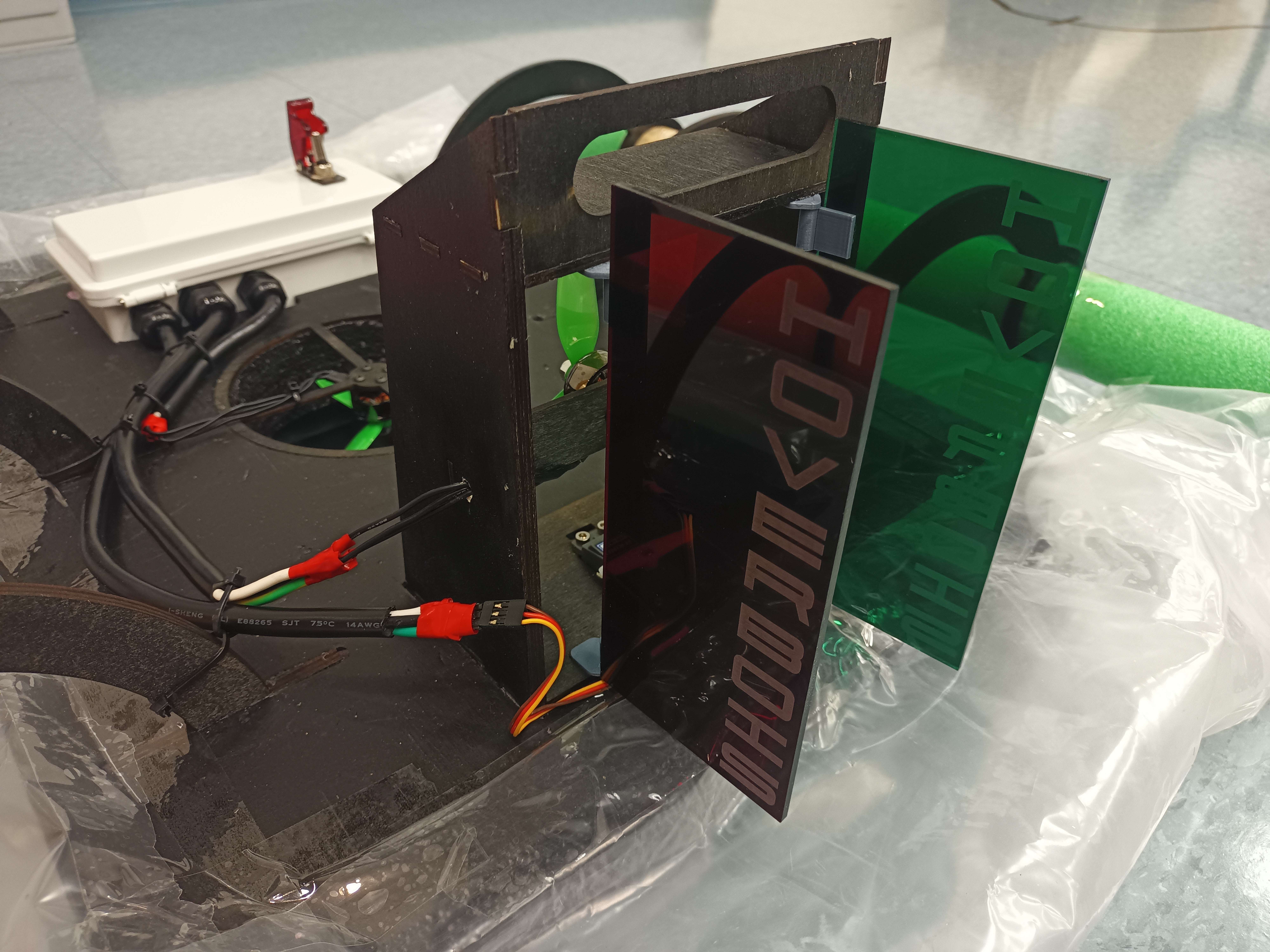
Dual rudders are mounted to the superstructure via Pintle and Gudgeon hinges. We chose a dual rudder design for improved control authority at low speeds, as we found a single rudder insufficient for this in prior iterations. The Pintle and Gudgeon hinges are 3D printed and constrain the rudder in all degrees of freedom except rotation about the vertical axis. The rudders themselves were CNC lasercut from acrylic for water resistance and durability.
The thrust motor is mounted to a cross-bar element between the sides of the superstructure via four 3mm machine screws. The superstructure acts as a 4-sided enclosure around the propeller to protect it from splashes and debris, and also to project the operators from the spinning blades.
The handle is mounted to the top and sides of the superstructure and provides a hold to arrest the motion of the vehicle in the event of loss of control. The top of the superstructure shields the operator’s fingers from the propeller blades when grabbing the handle, and the robust mounting of the sides of the superstructure ensures transfer of load to the chassis.
The superstructed is designed to leverage CNC lasercutter technology by utilizing finger and tab joints throughout. The cross-bar element is mounted to the superstructed sides with mortise and tenon joints, and the handle is mounted to the top and sides of the superstructure with tab joints. The rest of the superstructure is joined together with finger joints.
Outriggers
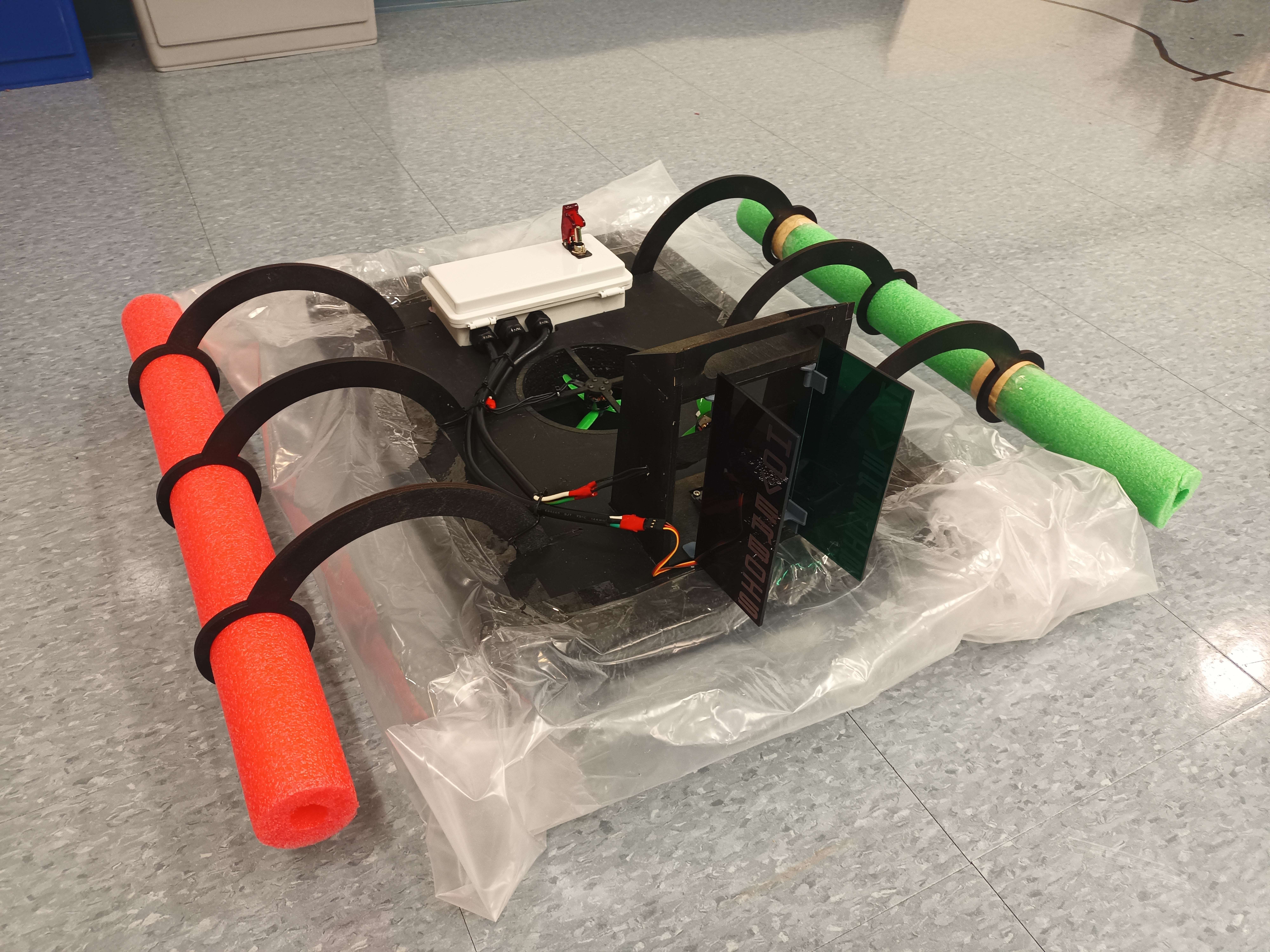 To provide positive buoyancy at all times to the hovercraft and to prevent the hovercraft from flipping, pool noodle outriggers were built to provide security on the water. The outriggers are mounted into the foam using a series of six laser-cut plywood holders, three on each side of the hovercraft. Three mounts on each side ensure reliable and stable flotation, even if a few fail. The mounts were designed to hold the foam pool noodles about 3 inches from the edge of the inflated skirt. The holes were cut to the size of the pool noodles to ensure a tight fit, and the pool noodles would not slip out, ensuring there was security for stability on the water. In addition, the design of plywood mounts was built so that the outriggers don’t touch the ground when on land. This guarantees true amphibious capabilities as the outriggers would only be used on water.
Waterproof Electronics Enclosure
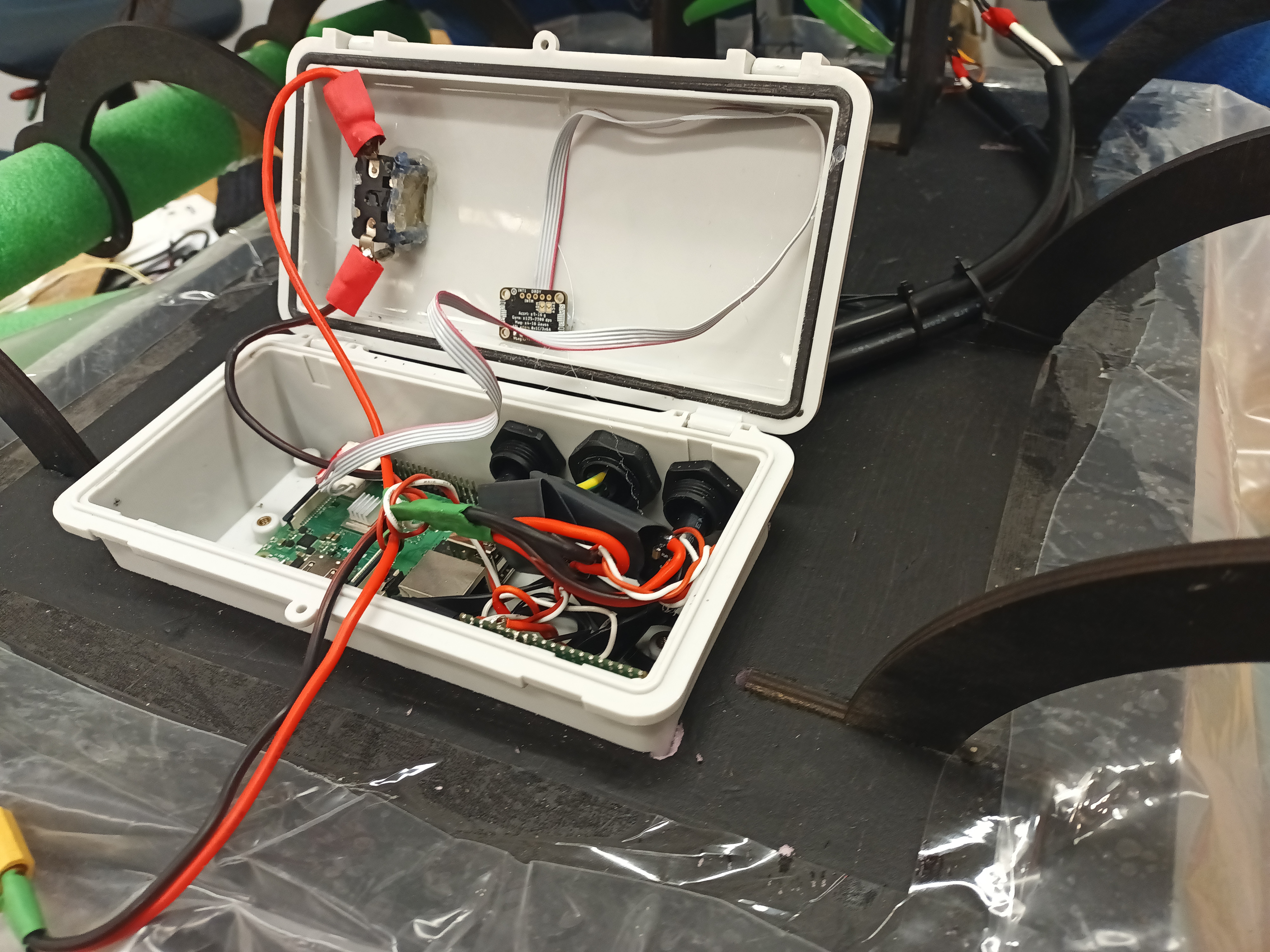 To protect the electronics from the aquatic environment, even in the event of a capsize, all electronics except for actuators are inside a waterproof enclosure. The electronics bay primarily consists of a COTS waterproof enclosure that has a waterproof rating of IP65 and utilizes a gasket seal.
Inside the box are the motor ESCs, LiPo battery, 9 Axis IMU, and GPS module. All of these items are critical to the functionality of hovercraft. These electronics are all connected inside the box and to the actuators through three COTS pass-thrus. Only three cables exit the box, and the pass-through tightly cinch around the cables. In addition, there is an Estop mounted to the top of the box so the hovercraft actuators can be switched off mechanically.
Waterproofing
Waterproofing all hardware was a central aspect of the design methodology. We painted all wood parts and sprayed them with clear water-proof sealer. We were thoughtful to eliminate all water-vulnerable materials by use of waterproof substitute materials such as acrylic and CoroPlast. We also waterproofed the servo motor by plasti-dipping it. The choice of brushless motors meant that we could leave them uncoated without introducing a vulnerability in our use case of a freshwater environment.
Weight and CG
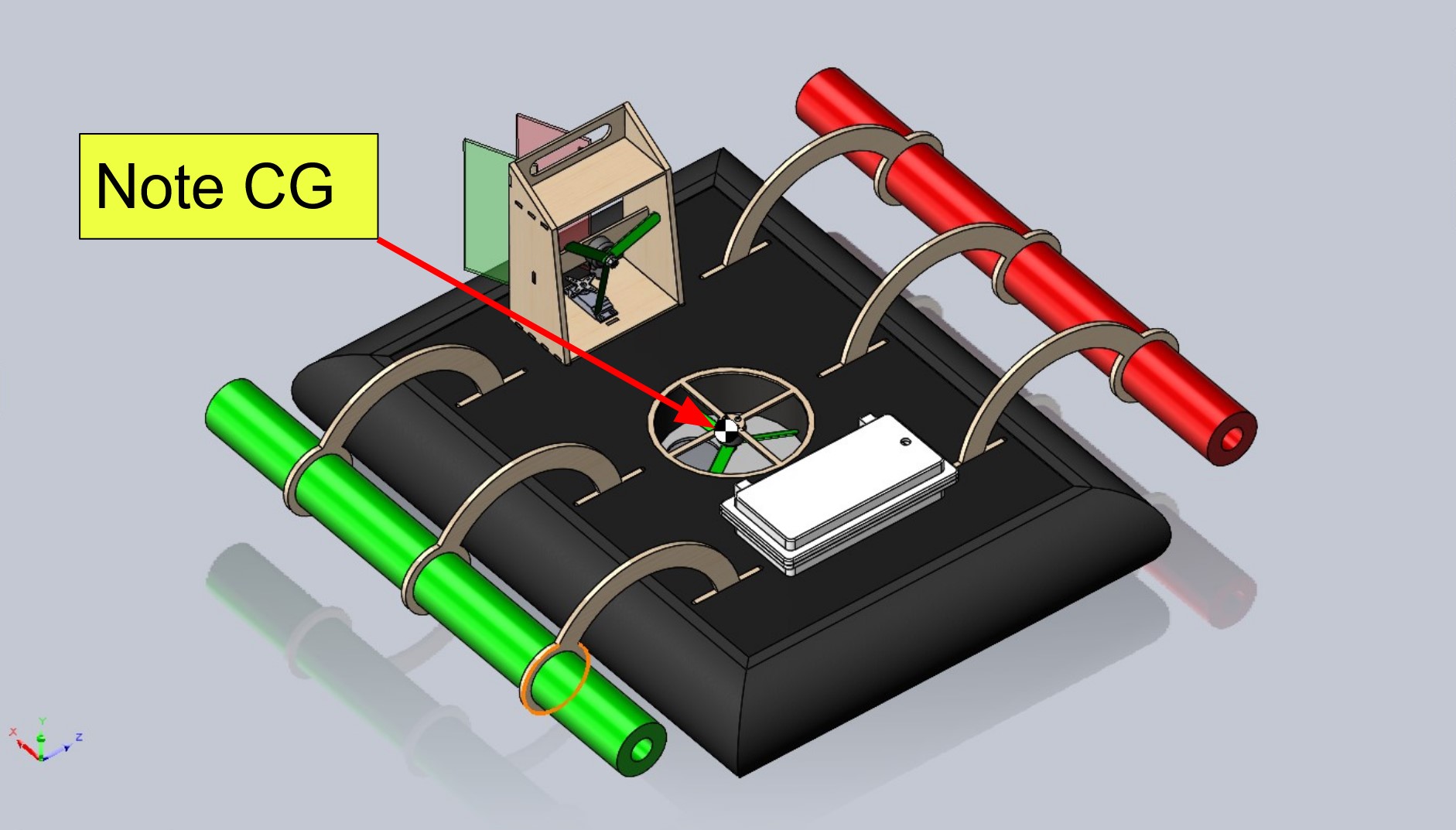
Throughout the mechanical design process, we were careful to minimize weight and ensure the center of gravity (CG) was located under the lift motor. To do this, we used Solidworks mass properties to keep track of the weight and CG during the CAD stage of the design process. We confirmed these calculations with a fingertip center of gravity test once we finished fabricating.