Evolution
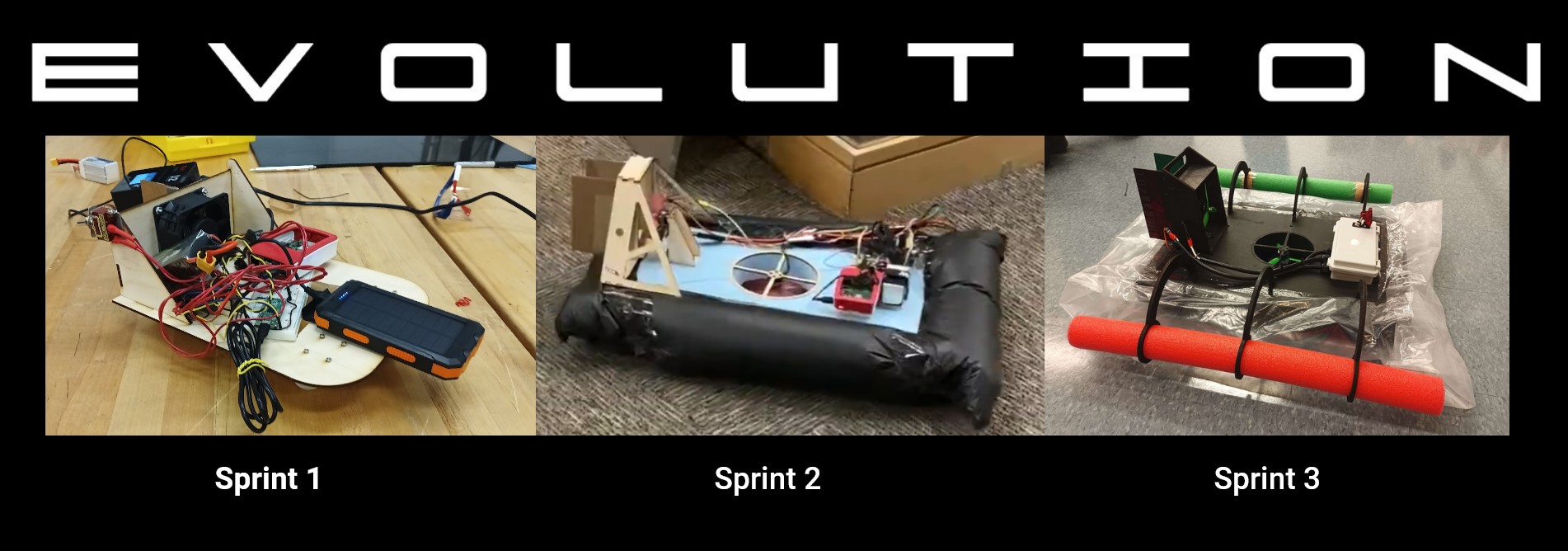
Over the course of this project, we used an agile development framework to iteratively design our vehicle. Using the SCRUM method, we split the project up into three “Sprints,” with increasing fidelity towards our final goal. At the start of this process, we identified technical risks that the project as a whole faced, and we targeted our sprints to elliminate these risk factors in stages.
The factors we identified included:
- Rudder mechanical design and software control
- Low-friction vehicle control
- Hover ability
- Aquatic environmental factors
Sprint 1
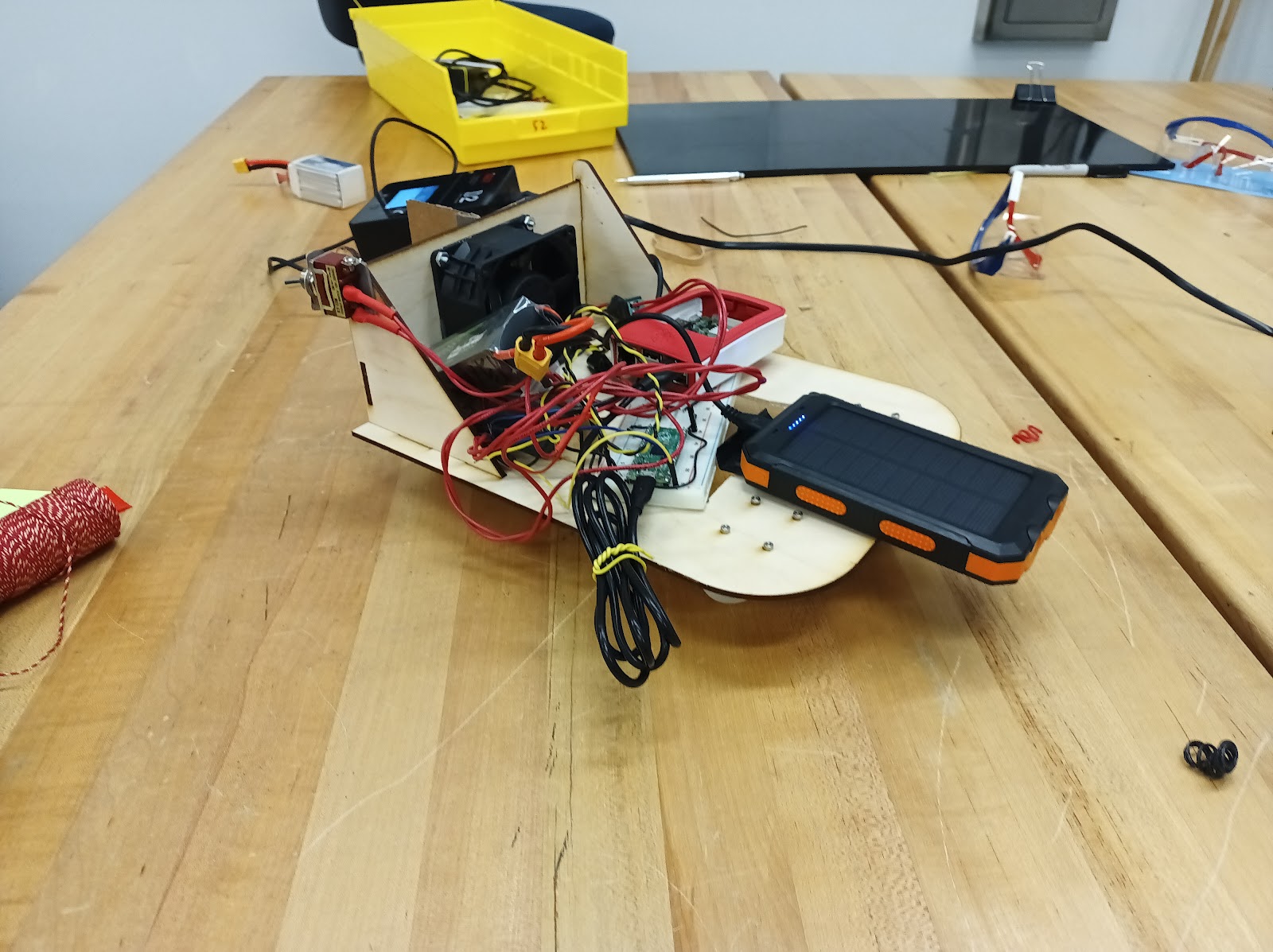
Our goal for Sprint 1 was to create a fan powered kart that was controlled via a rudder. We knew that in order to accomplish this, we would need to gain familiarity with the electrical system for fan-powered vehicles, estabilsh our software architecture to control a low-friction vehicle via rudder, and develop a workflow to collboratively CAD and manufacture an air propelled vehicle.
Mechancial Progress from this sprint included developing a workflow to collaboratively design and manufacture a chassis for fan powered vehicle, design and fabricate a rudder steering system, and create hardware that integrates with the electrical propulsion system. Mechanical lessons we learned from this sprint included the importance of a more authoritative rudder for control, and the importance of planning how to distribute electical hardware about the vehicle’s center of gravity.
Electrical Progress from this sprint included gaining familiarity with the drivers and motor controller, and speccing and ordering the high-performance electrical components of the final propusion system for use in Sprint 2 and Sprint 3. Lessons learned from this sprint in the electrical domain included order parts sooner and go with a better Raspberry Pi.
Software Progress from this sprint included creating the website backend for controlling the vehicle over wifi, implementing a Discord bot to communicate the IP address for autostarting, and creating the framework of having two onboard micro-computers: a Raspberri Pi and a Pi Pico. The Pi runs the high level software, and the Pico runs the low level motor controll. Software lessons learned from this sprint included the importance of codebase organization and code readability.
Primary Outcome of this sprint was that we eliminated fan propulsion and rudder control as complete unknowns. By applying the lessons from this sprint to our next sprint, we were able to make improvements to existing systems based on experience and introduce the element of hover without simultaneous risk factors. In addition to overcoming technical challenges, our team used this sprint to hone our soft skills and establish practices for how best to work with each other for the rest of the semester. One of the outcomes of these discussions was to estabilsh a rotating Project Manager position for the next two sprints.
Sprint 2
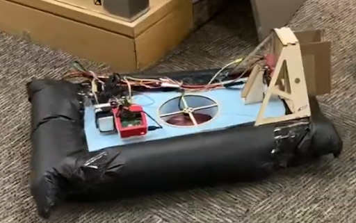
Our goal for Sprint 2 was to create a remote controlled terrestrial hovercraft with inertial PID correction for straight-line autonomy. We knew that in order to accomplish this, we would need to implement the high-performance electrical propulsion system we ordered during Sprint 1, develop software to correct for inherant instbility based on inertial sensor input, and create a hover system and chassis that matched weight with power and could sustain hover.
Mechanical Progress from this sprint included creating a lightweight hovercraft chassis and an efficient hover lift system. The implemented system was able to sustain hover for long periods and at high speeds. To accopmlish this, we selected a closed plenum design and made the descision to machine the chassis from lightweight foam. Based on the lesson we learned from Sprint 1, we also implemented a dual rudder design for improved control authority. In addition, we created a mechanical design that integrated well with the new high-performance electrical system that we had ordered the prior sprint. Mechanical lessons learned from this sprint included the need to eliminate slop from the rudder hinges.
Electrical Progress from this sprint was centered around implementing the high-performance electrical system we had previously ordered. This electrical system was based on design paradigms from the feild of aerobatic drones, and was accordingly super lightweight and incredibly powerful. The brushless motors and ESCs can reach a fast speed at only 15% power, despite being a fraction of the weight of the fans from Sprint 1. Integrating these motors required using a PWM signal, and learning how to implement these with the Pi + Pico microcomputers. We also added an improved electrical EStop switch. Unfortunately, lose wires and the IMU fell into the hover fan—a near catastrophic accident. Electical lessons from this sprint included cable management and mechanical/electrical integration are essential for safety.
Software Progress from this sprint included the implementation of a vastly improved control system and inertial correction for straight lines. The inertial correction input from an IMU and moves takes corrective action based on a PID loop. This system corrects the vehicle’s course to a straight line when the pilot removes turn input. We also created software that can simultaneously manage both the lift and thrust brushless motors, as well as a software E-Stop. Sofware lessons learned from this sprint included the need for a faster, more robust communication method than wifi. We found our high-speed terrestial application was pushing the limits of our wifi communication, and this latency and unreliabilty presented an unacceptible risk for our next step of operating in an aquatic environment. We also realized the need for analog control inputs by the pilot for steering.
Primary Outcome of this sprint was that we conquered the challenge of getting the vehicle to hover. We also established a baseline design from which we could improve reliabilty to reach a point that could operate in an aquatic environment. We found that our rotating project manager system was a sucess, and chose to move forward with that system for the next sprint by electing a new project manager as planned.
Sprint 3
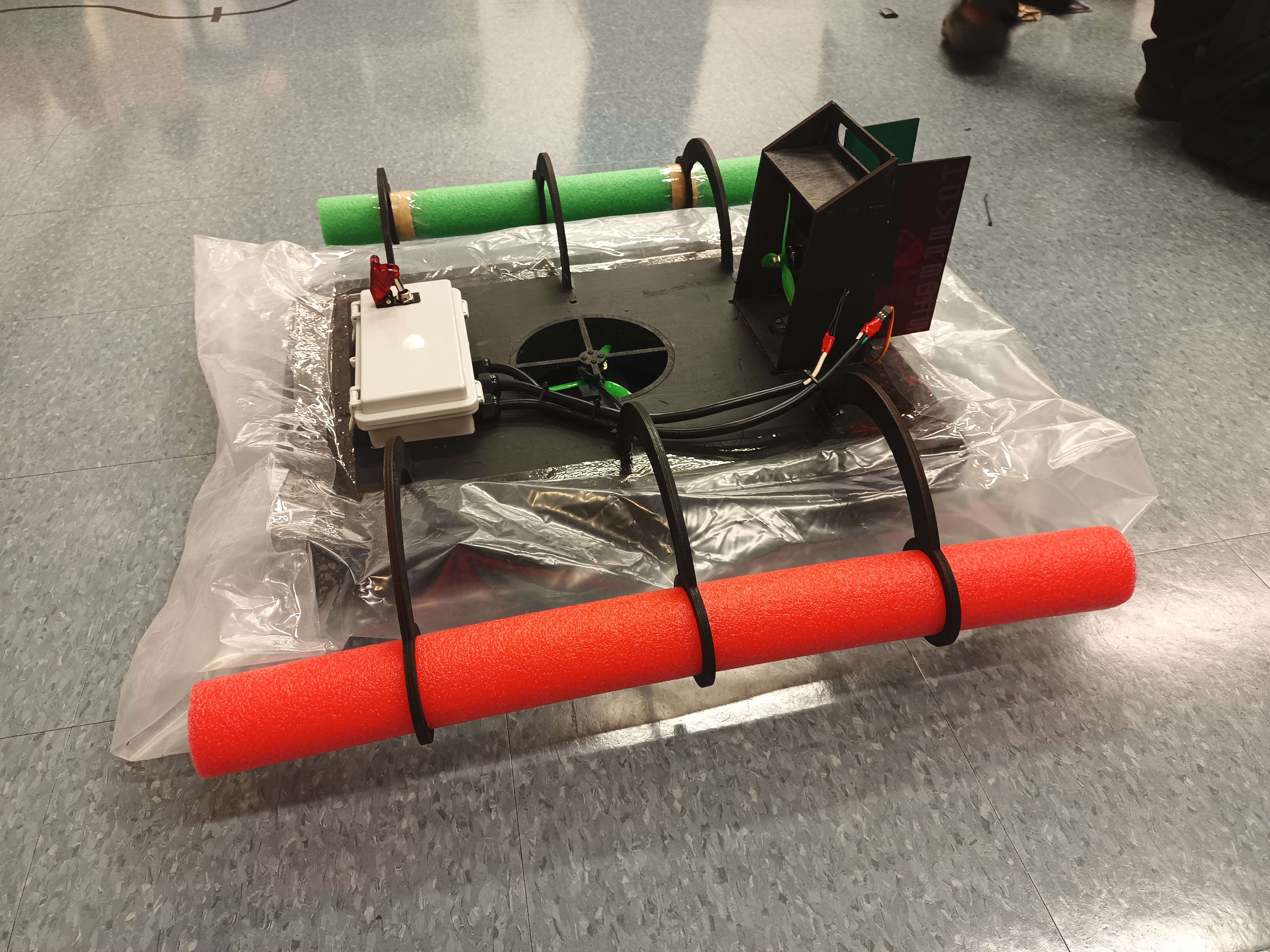
Our goal for Sprint 3 was to make an amphibious hovercraft capable of operating in both terrestial and aquatic environments. We knew that the main technical risks for this sprint were around the element of water, including: capsizing, sinking, water shorting electronics, loss of communications while on the water, and loss of controll while on the water. We made special care to target this sprint towards managing those risks.
Mechanical Progress from this sprint included a complete mechanical redesign of our vehicle, now dubbed “The Waterstrider”. The redesign built on our previous sucess by incoperating improvements in reliability, as well as adding new features to combat the risks of the aquatic environment. We added auxiliary outriggers as a safety measure against capsizing, eliminated water-vunerable materials, and housed the electrical system in a waterproof enclosure. We also waterproofed every component with sprays, dips, or by choosing an inherantly waterproof substitute material.
Electical Progress from this sprint was centered around adapting the electrical system so that as many components as possible could fit into the waterproof electronics bay. We were able to redesign the system such that the only electronics outside the enclosure were the brushless lift and thrust motors and the servo motor. All electrical connections between the inside and the outside of the enclosure are via three multi-conductor cables, which gain access to the box via COTS waterproof pass-thrus. We attempted to implement a new communication system based on a radio; unfortunately, our radio unit was of poor quality and fried itself. Electrical lessons learned from this sprint include integrate earlier and invest in quality electronics.
Software Progress from this sprint was centered around critical improvements to the control system. The first overhaul was the implementation of analog pilot input via a bluetooth controller. We found the previous sprint that digitial turn inputs made the vehicle difficult to control, which would present a risk when operating on water. The new analog control interface lets the pilot give continuous turn input for smooth control ameanable to an aquatic environment. The second major upgrade was switching from wifi to bluetooth for communication. Loss of communication on land during Sprint 2 was an inconvenience, but loss of communication on the water would be catastrophic. The new communication also implemented a novel bug fix that decreased latency from several seconds to unnoticeable levels. We also upgraded to a full fly-by-wire control system that uses IMU data and a PID loop to hold the vehicle’s angular turn rate at a setpoint dictated by the continuous input of the pilot.
Primary Outcome of this sprint was that we conquered the challenge of making our vehicle fit for the aquatic environment. We conducted sucsessful on-water and terrestrial tests to demonstrate true amphibious capability. The Waterstrider design at this point reached a state that was ready for demo day. Our rotating project manager system was again a sucess, and we also had sucess adjusting our expectations of eachothers work commitments to be more flexible for a less tense teaming experience.