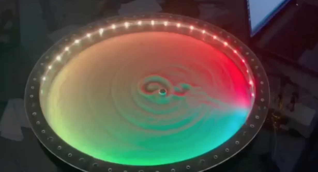
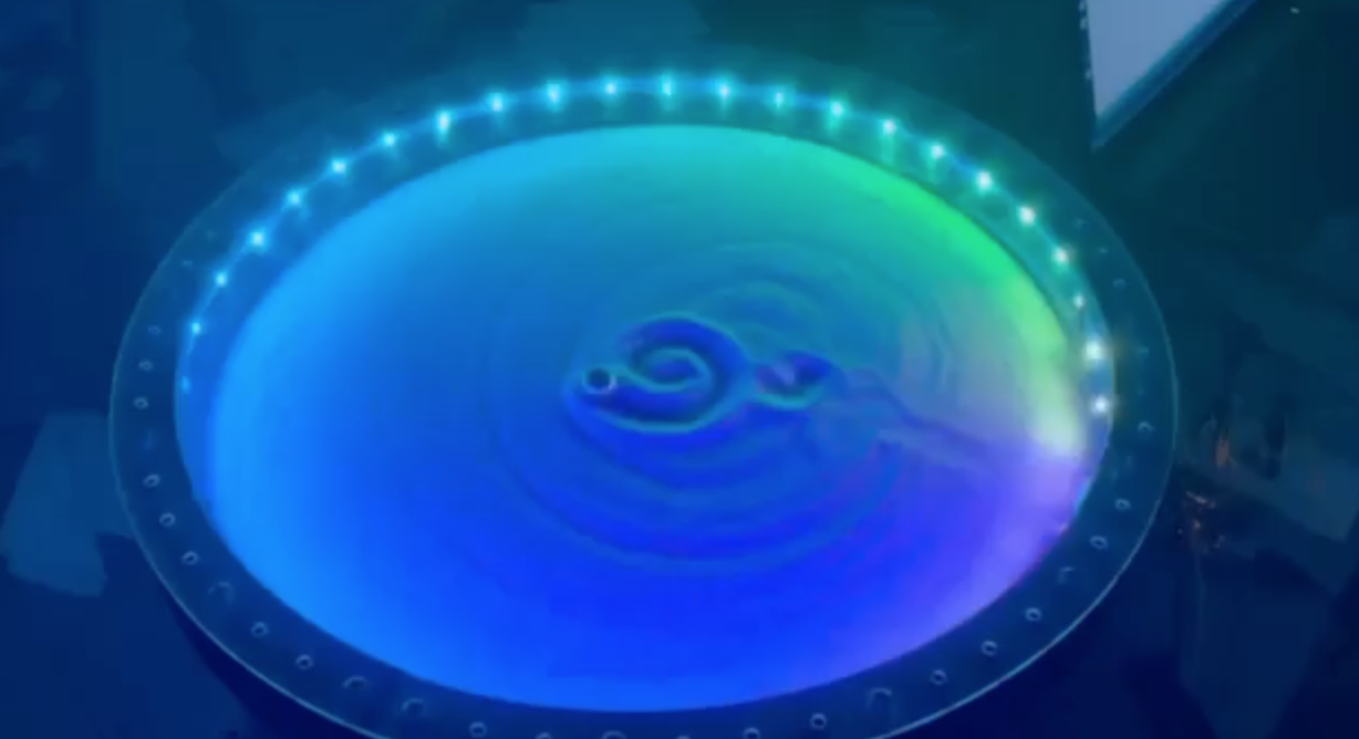
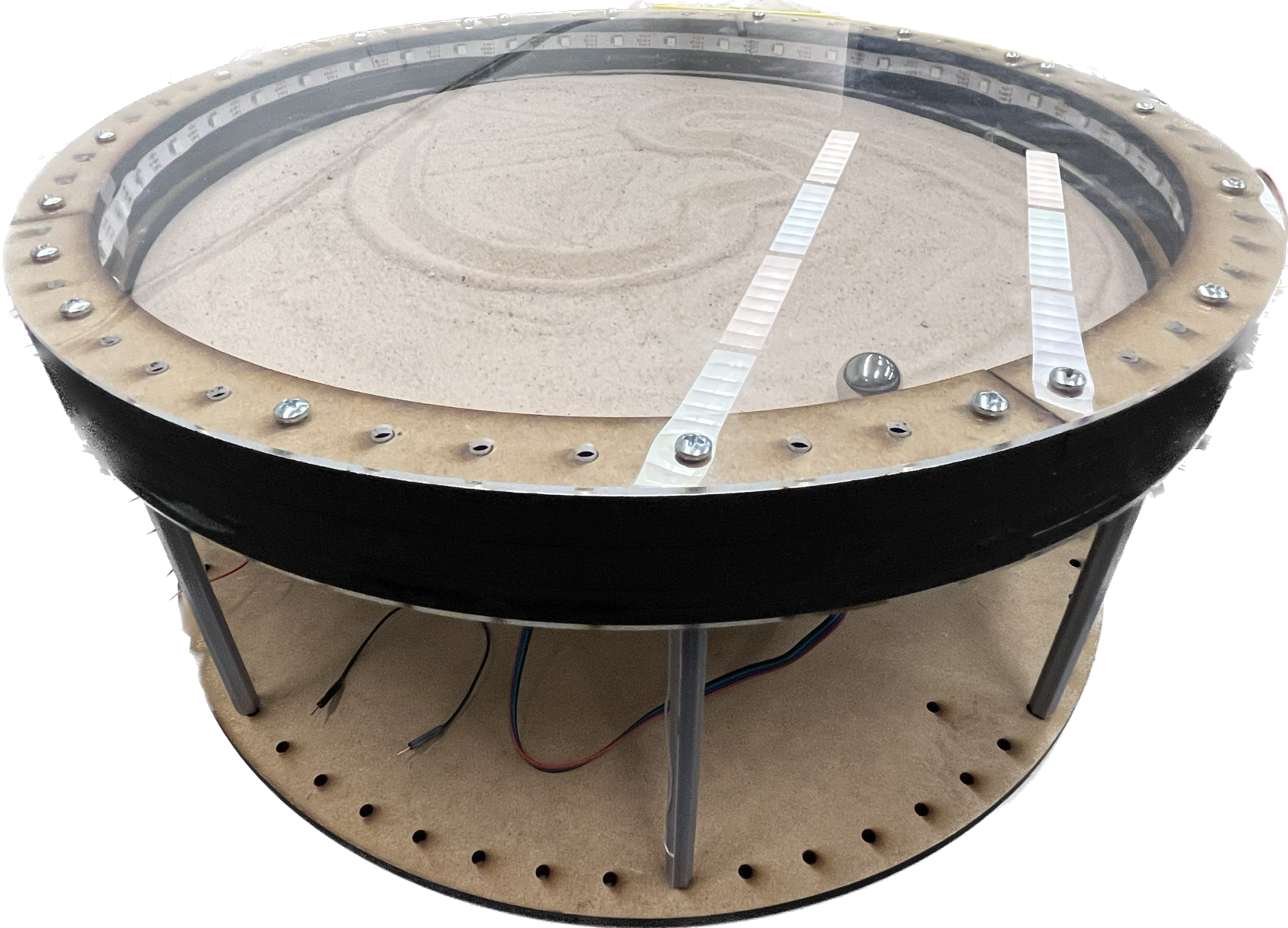
A zen garden that draws itself. A steel ball moves around a flat sand bed via a magnet underneath, drawing different continuous patterns.
High level overview of the system.
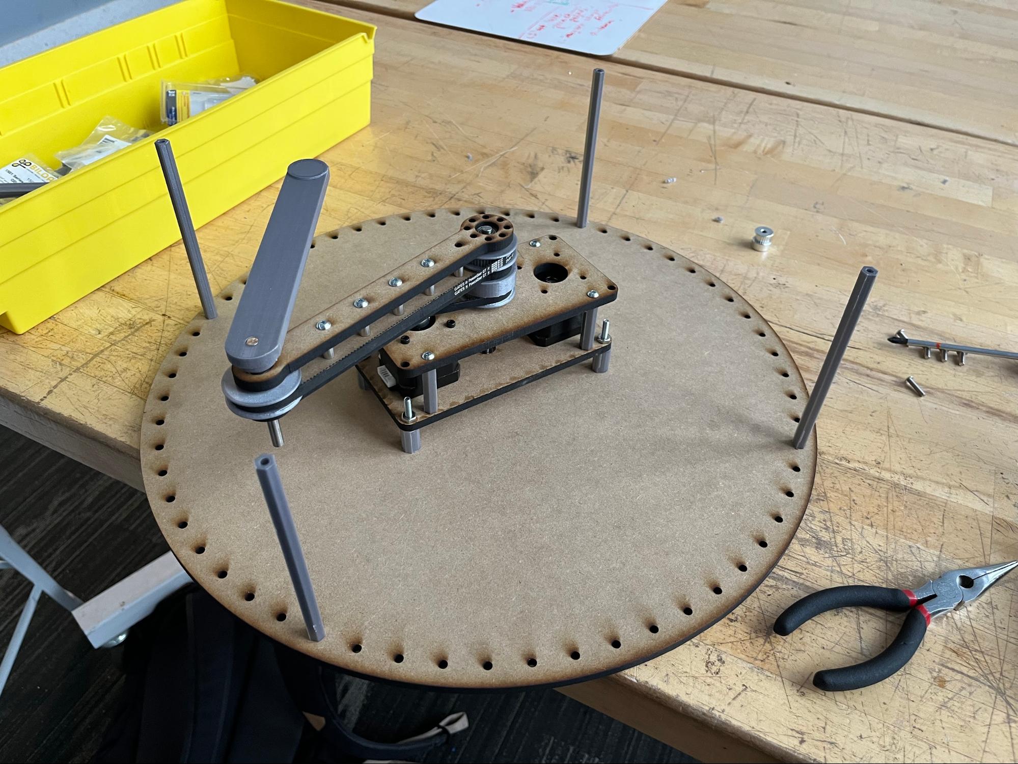
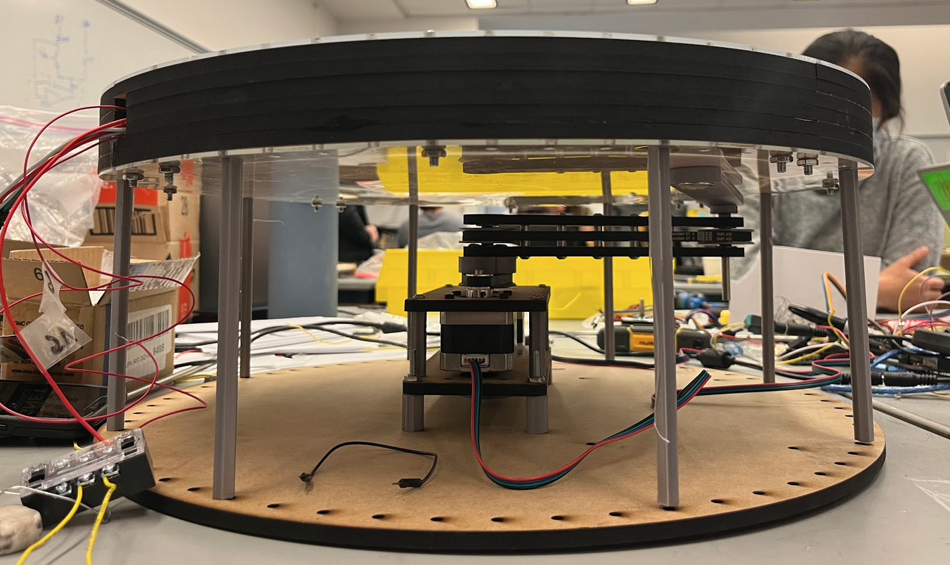
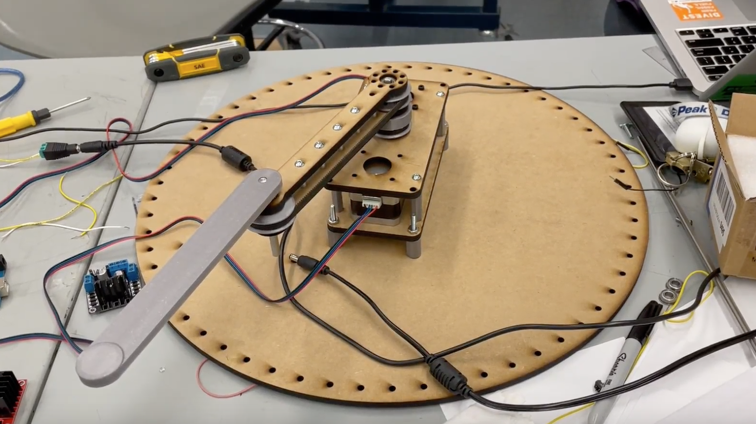
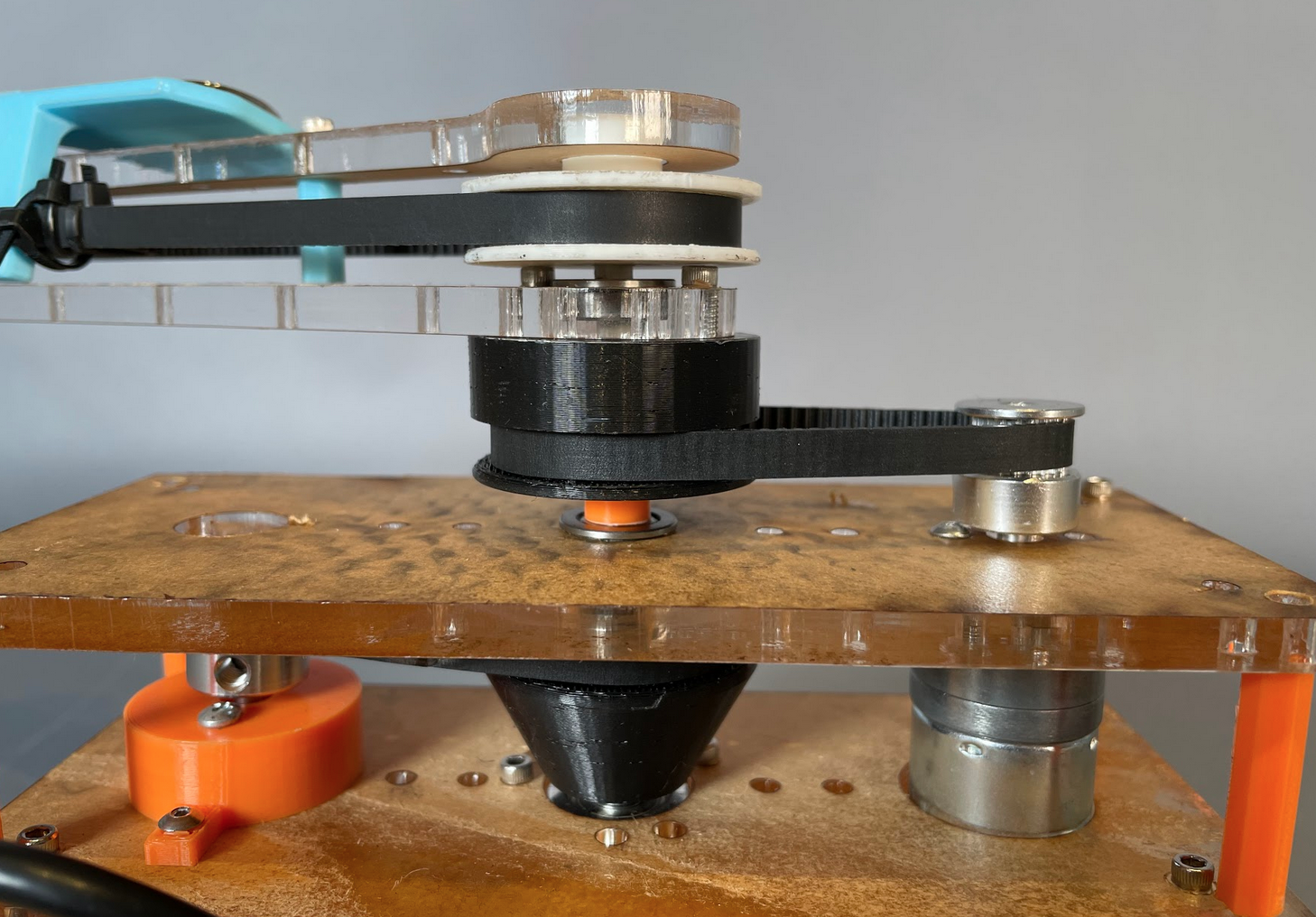
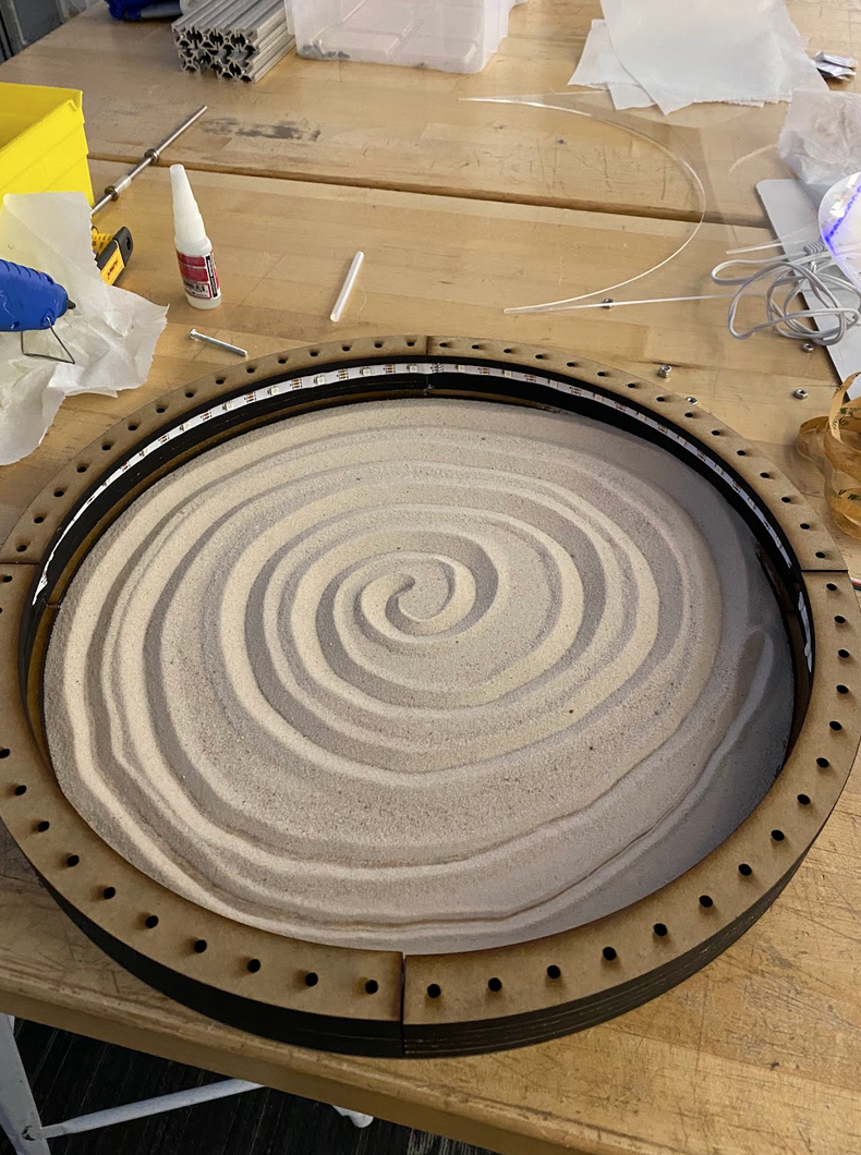
Uniaxial arm and sand enclosure.
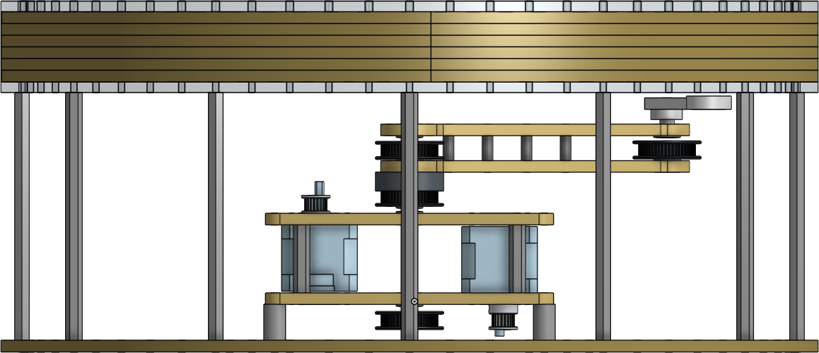
The mechanical design consists of three main parts: the uniaxial arm, the sand enclosure, and the electrical containment. The goal of the mechanical design is to use a magnet to seamlessly move the ball anywhere within the sand enclosure based on what the software maps it to.

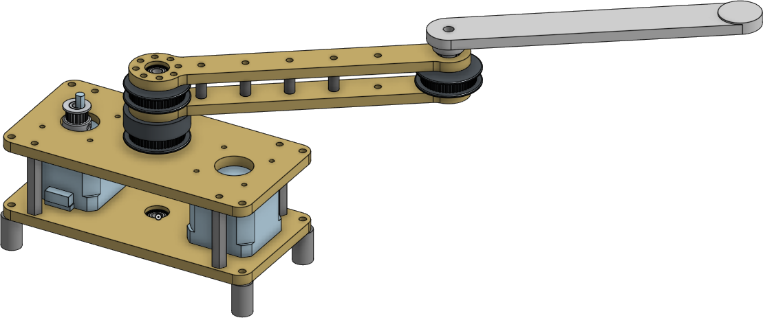
The uniaxial arm controls both the rotational motion and the axial motion through a single axis. This, as opposed to an x-y gantry, allows us to keep the enclosure contained to a circle. We used timing belts around the pulleys to control both arms separately. The rotational motion arm and the plates holding the motors are laser cut ¼” MDF. The axial motion arm and the black pulleys are 3D printed. All other parts, including the standoffs, shafts, and metal pulleys are all COTS (Commercial Off the Shelf) parts.
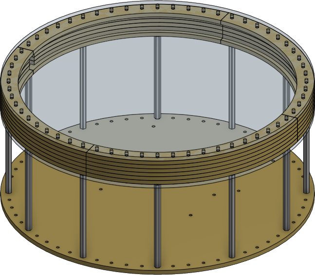
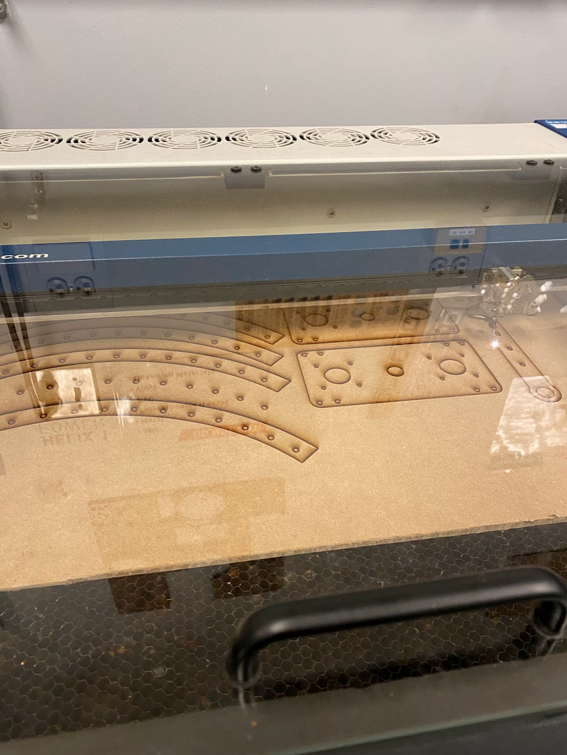
To make the walls that enclose the sand, we divided the circle into four parts and used ¼” MDF which was bolted and glued together. In order to save material and create room for LEDs that stuck to the inner walls of the enclosure, the width of the walls varied as shown below.
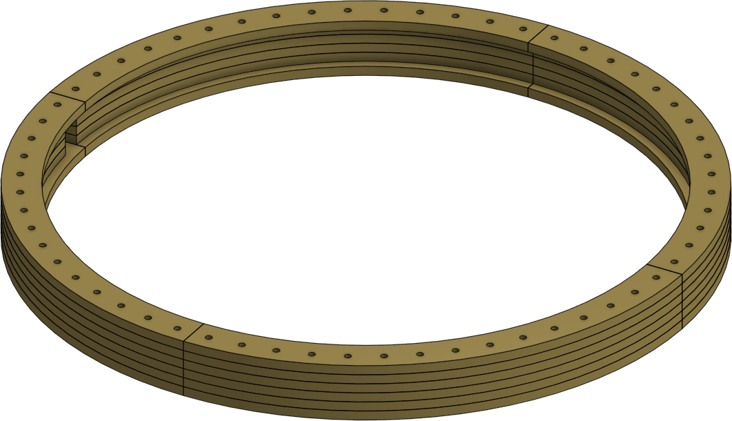
On each side of the sand walls, we used 2mm clear acrylic, so that it was see through on the top, and because 2mm was a proper thickness to hold up the sand while still allowing the magnet to work smoothly. In order to keep the sand enclosure at an appropriate height above the magnet in the arm, we 3D printed standoffs.
To keep the arduino and breadboard contained underneath the sand enclosure and not interfering with the arm, we decided to go simple by using double sided tape to hold the boards down and zip tying the wires to keep them from sticking up.
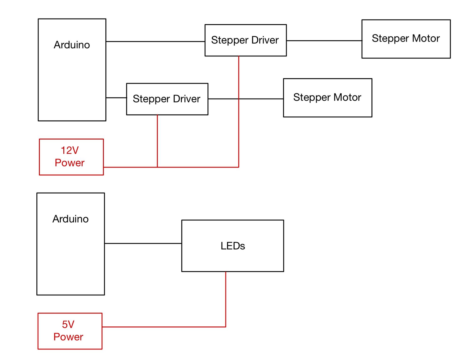
Wiring diagram and list of components.
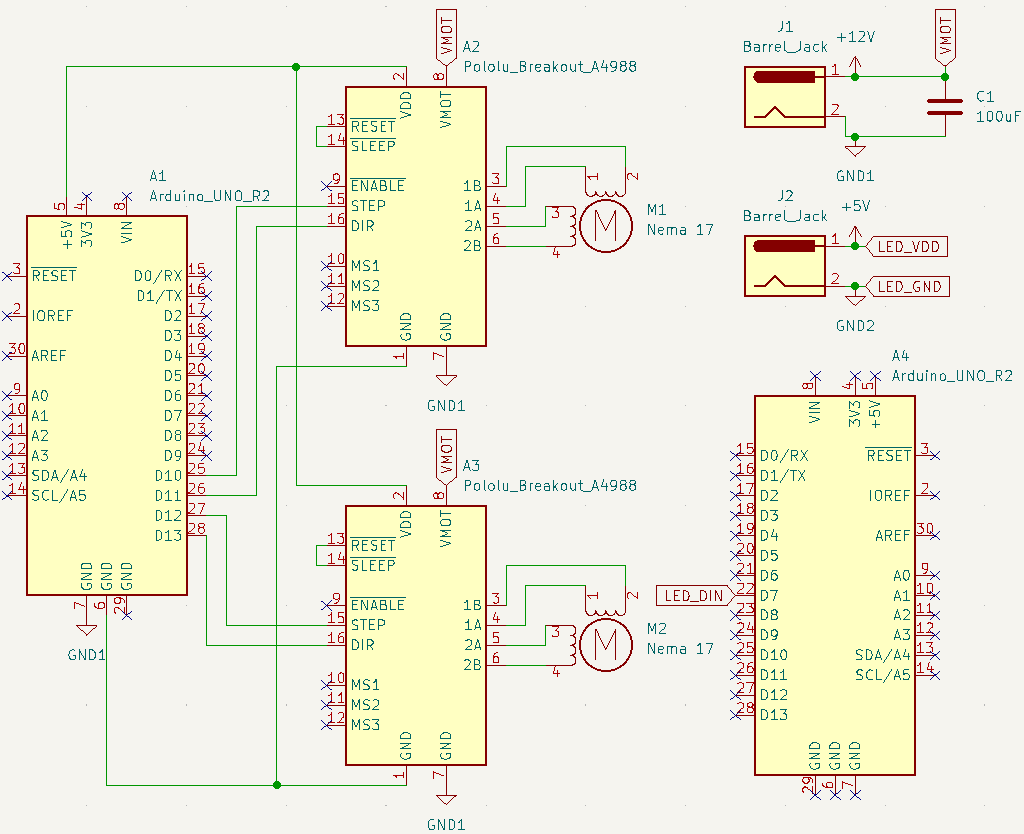
The electrical system of the sand table consists of two main sections. The first part consists of two Nema 17 stepper motors, two A4988 stepper drivers, and an Arduino to control the drivers. We used a 100µF bypass capacitor to smooth out the 12V power supply. The second part is the strip of LEDs, which has a 5V power supply and is controlled by a separate Arduino.
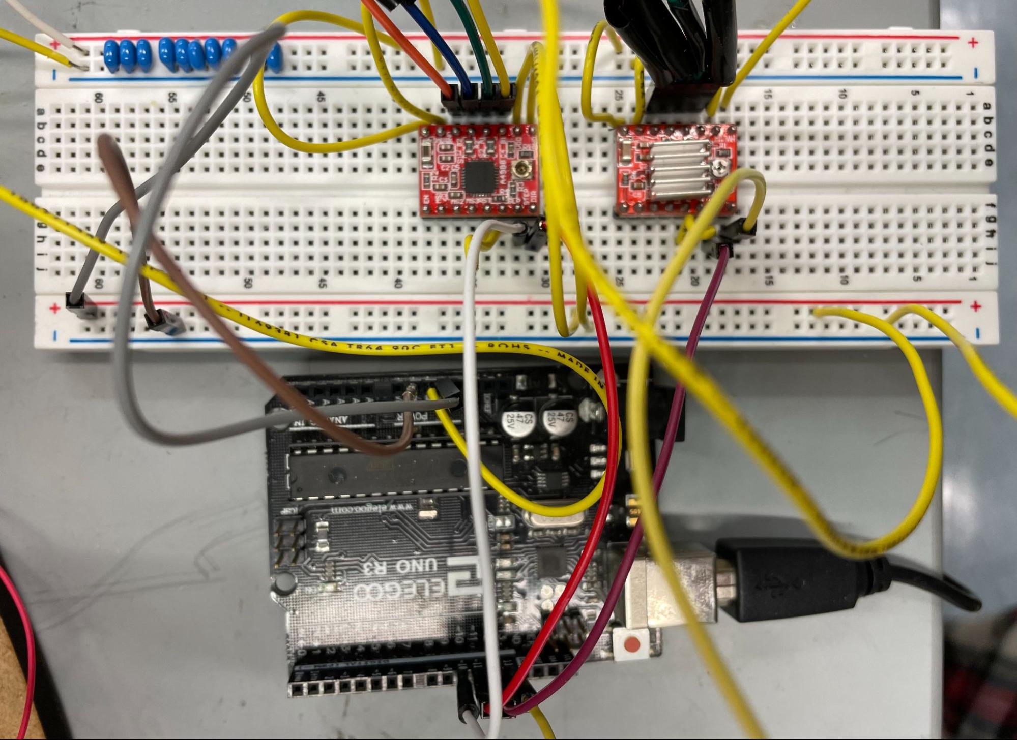
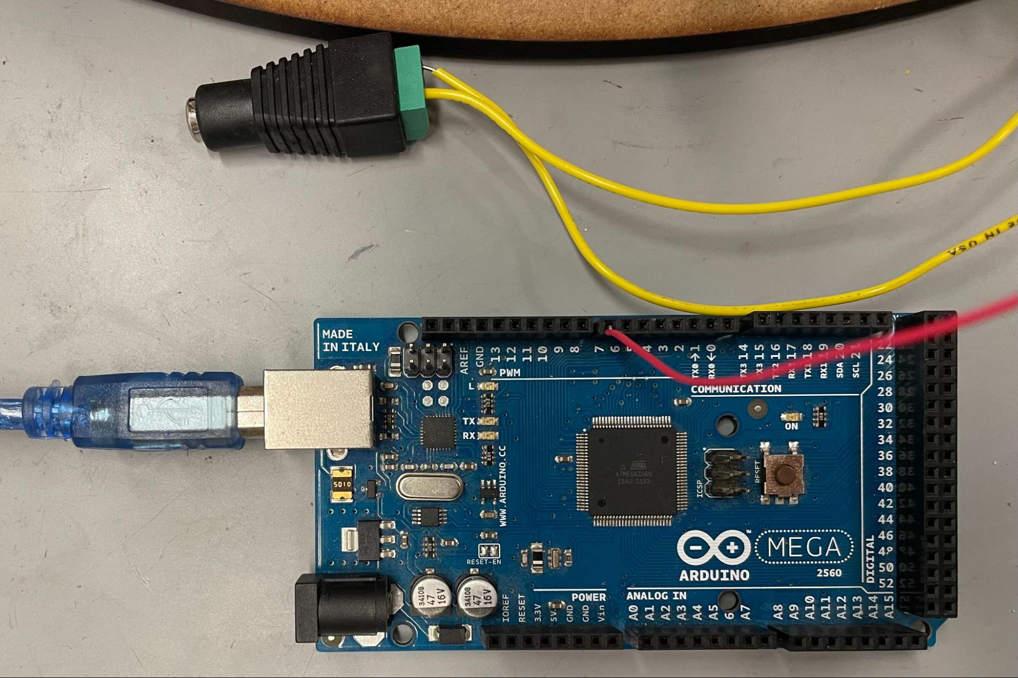
Stepper drivers and Arduino (left) and LED power and Arduino (right).
Controlling motors and LEDs via Arduino.
The software system runs on two Arduinos. One Arduino controls the LED strip and uses the FastLED library to run through a series of default patterns. The other Arduino controls the movement of the arm.
We use the AccelStepper library to control the two motors. The AccelStepper library provides the MultiStepper class which allows us to manage multiple steppers. The MultiStepper.moveTo() function allows us to move the two steppers at the same time for simultaneous motion. moveTo() calculates the necessary respective speeds at which the two motors need to move to reach their desired respective positions at the same time.
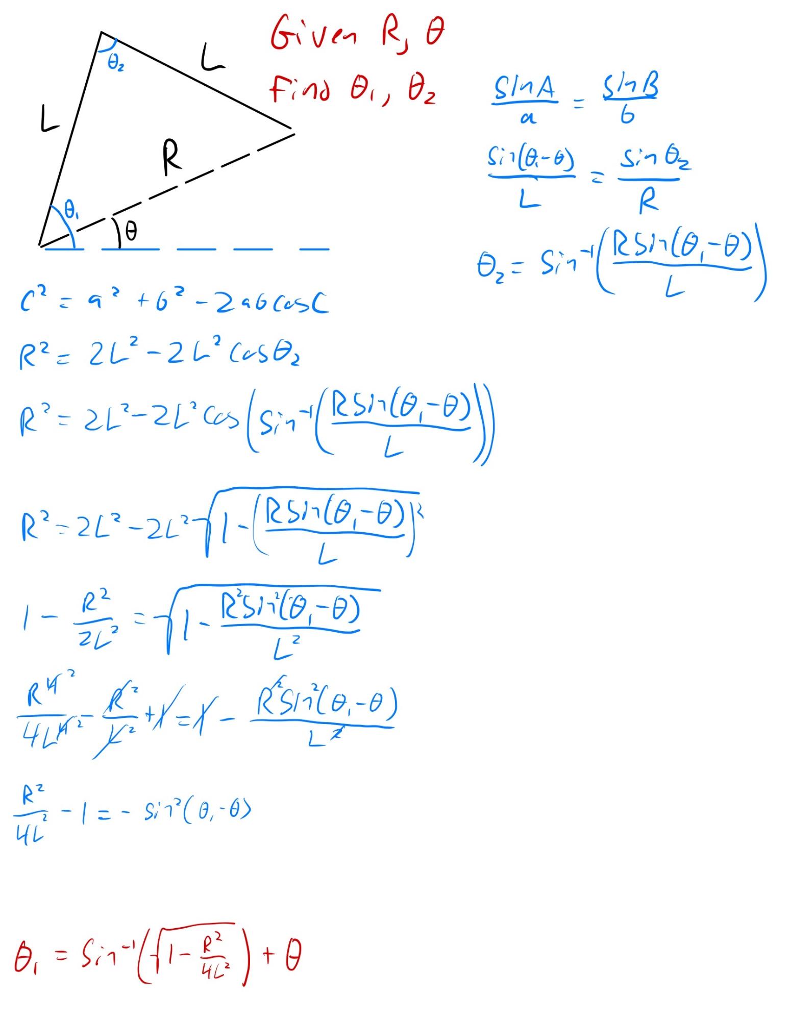
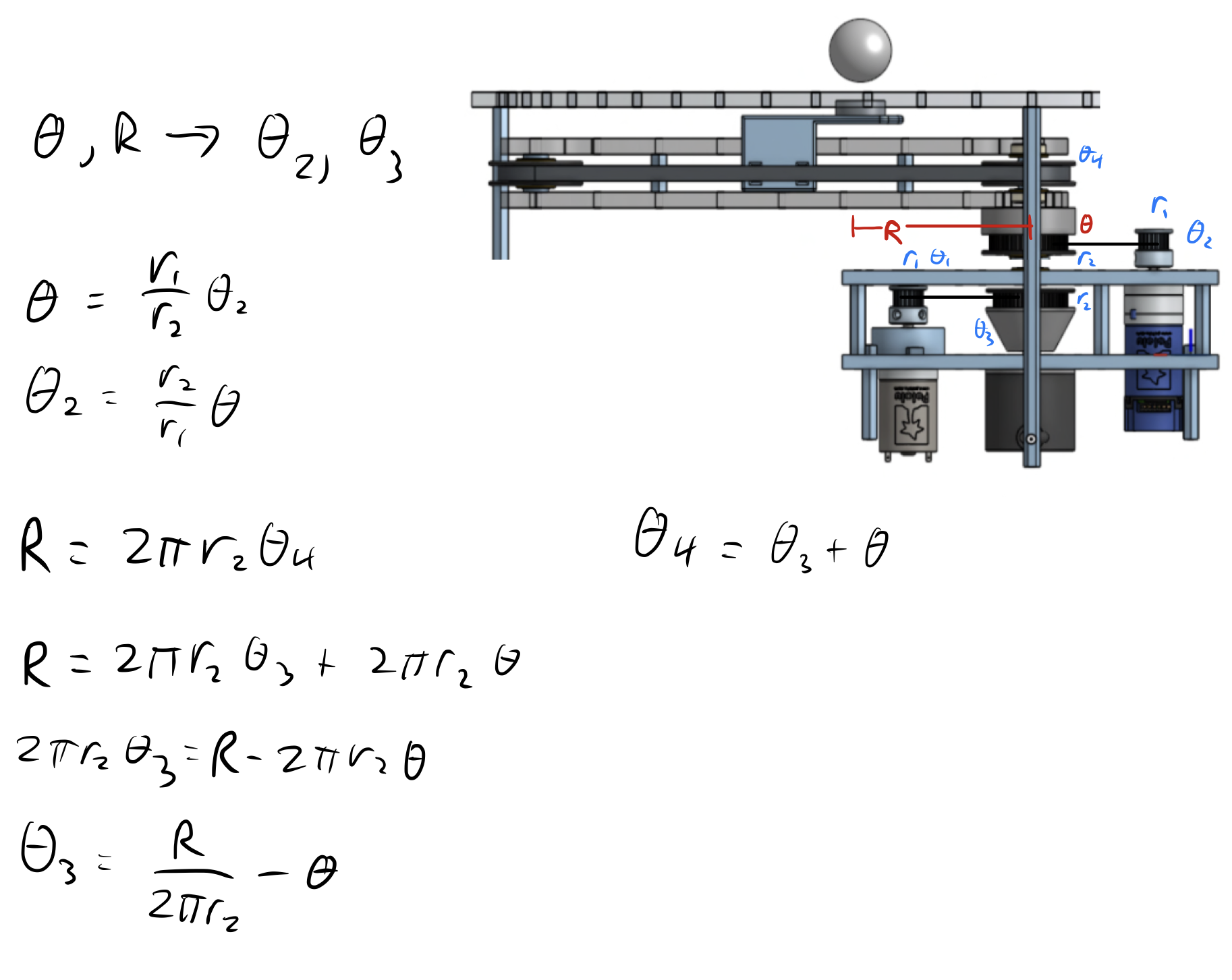
The way we create patterns in the sand is by moving the ball between points in small, discrete steps. The function that moves our stepper motors takes in the desired radius and angle of the magnet in polar coordinates and uses inverse kinematics to compute the necessary motor steps to reach that point. The inverse kinematics are necessary because both motors are on the same shaft—moving one motor moves the other.
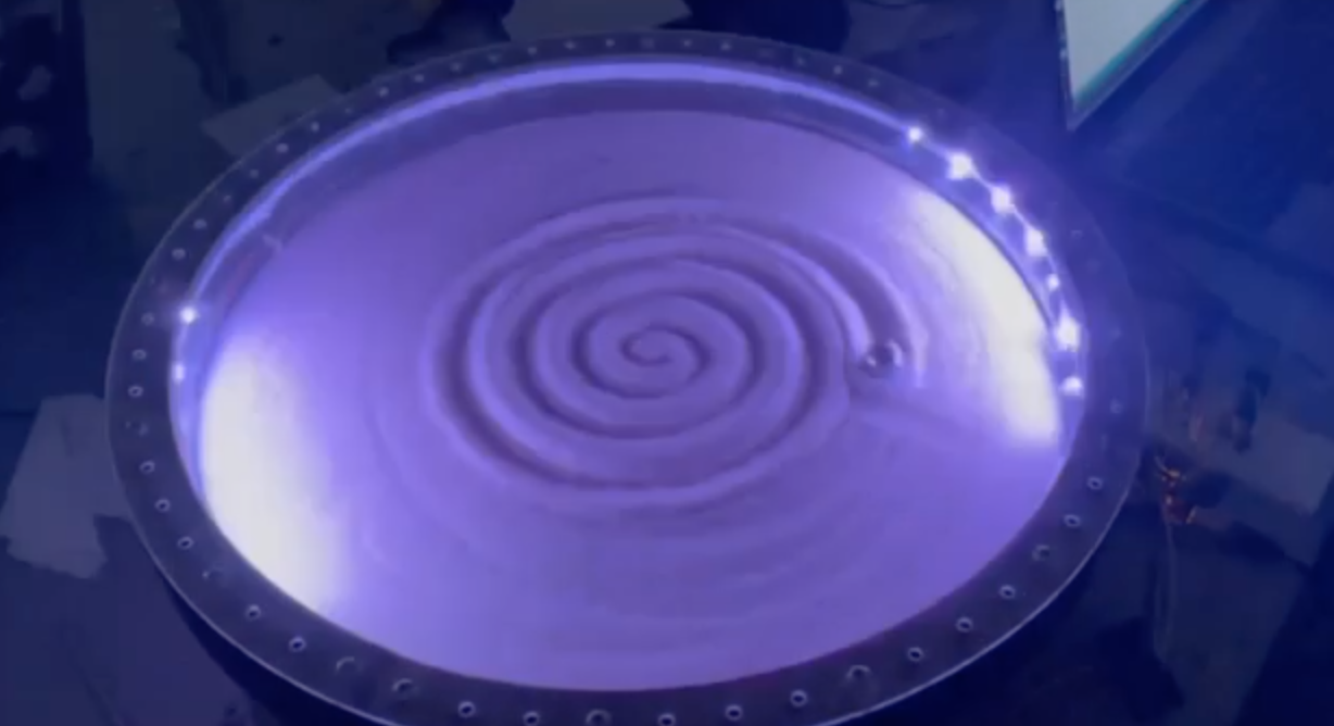
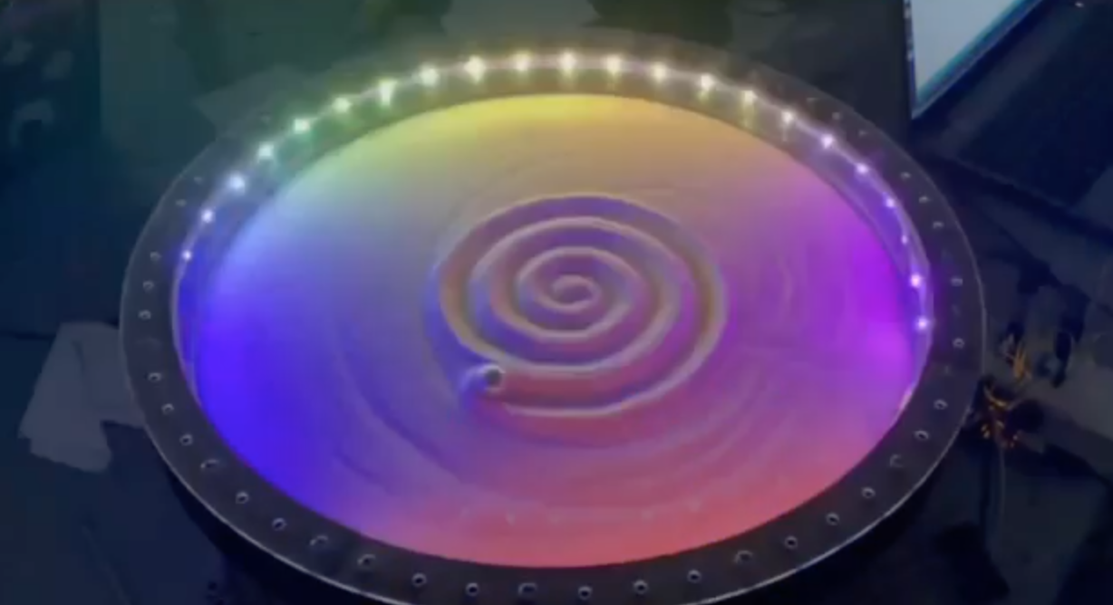
Rather than storing patterns as an array of points, we increase the angle in small increments of 5 degrees and calculate the resulting radius for the given pattern based on the current angle. A circle will return the same radius regardless of the angle, but a spiral pattern will increase and decrease the radius based on the current angle like so:
SPIRAL_SCALE * (currentAngle / 360.0) * MAX_RADIUS;
Where MAX_RADIUS is 165.0 * sqrt(2), and SPIRAL_SCALE is a value from 0 to 1 that determines the size of the spiral.
List of all parts and total project costs.
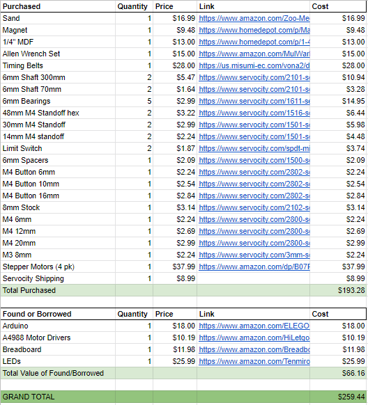
We were able to use scrap material we found and already had motors and an Arduino to use for testing in sprint 1 and sprint 2. For the final sprint, we bought materials for the final enclosure, which left us under the $250 budget. This included the MDF for the enclosure, timing belts, shafts, standoffs, bolts, spacers, stepper motors, sand, and magnets. We were able to either find or borrow the arduino, motor drivers, breadboard, and LEDs for the final design, so this didn’t exceed our $250 budget.
Prototyping a magnet movement mechanism and initial circuit with DC motors.
For the mechanical side on our first sprint, we focused on prototyping a magnet movement mechanism. We used existing DC motors and motors controllers for actuation and used a combination of 3d printed and laser cut parts to build the movement arm.
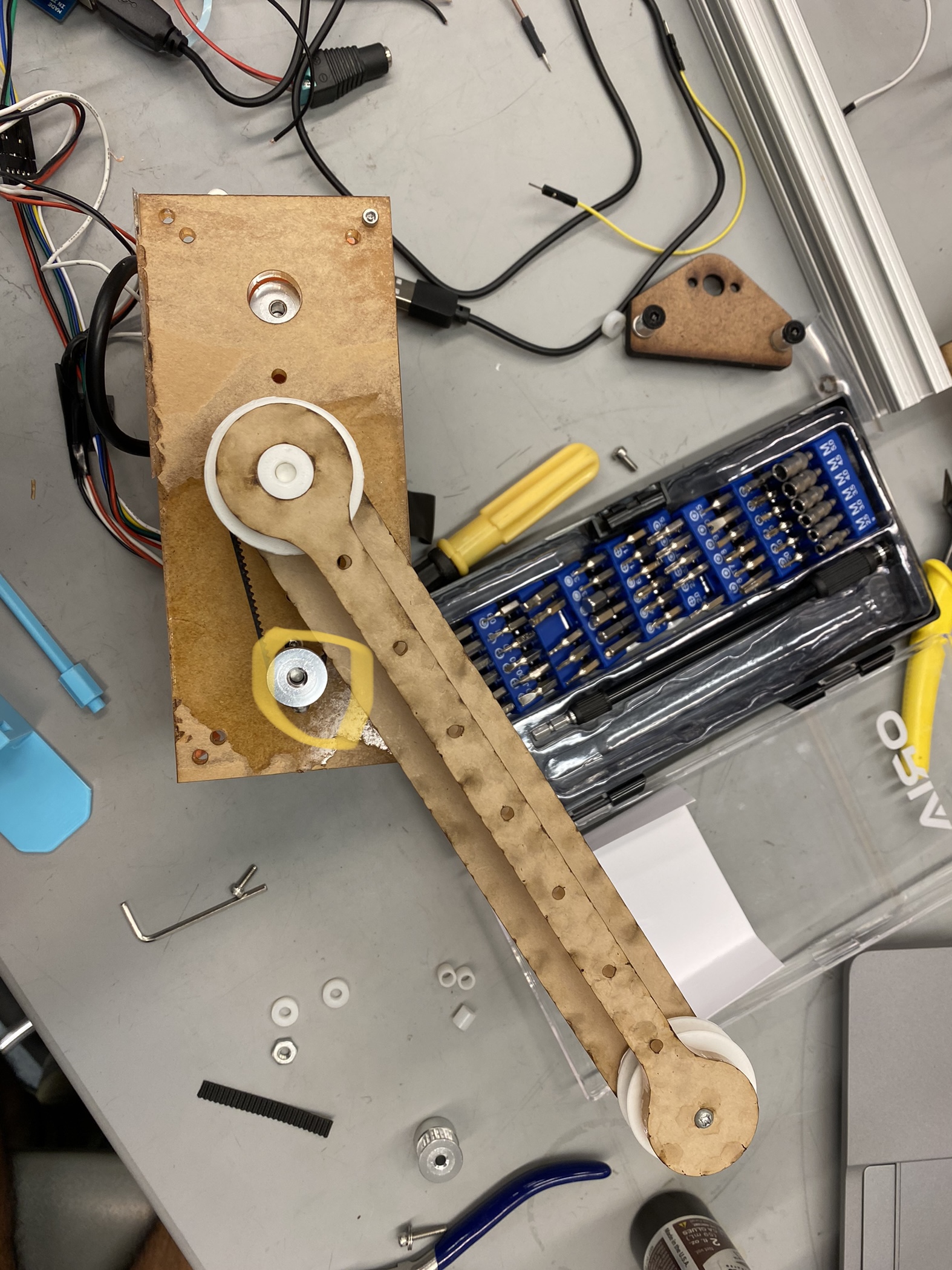
One primary design decision we made at the start was the need for a coaxial mechanism. By having both the actuation for radius extension and rotation on the same axis, we can eliminate the risk of tangled wires and reduce the required weight on the movement arm. The primary disadvantage with the coaxial design is an increase in complexity for the rotation system. We approached this challenge by using timing belts due to their lightweight and ease of construction with 3d printed pulleys. However, for our first iteration we aimed to purchase as few parts as possible, so we ended up making our own continuous timing belts which proved to be challenging.
Due to the small belt pitch, using pins to join the ends of the belt resulted in unreliable connections. We found that using CA glue and a piece of flexible cloth on the back of the belt produced the most consistent joins.
An additional issue we faced with our mostly printed design was our 3D printed axle bending. Below is a video of our sprint 1 mechanical iteration:
Much of the instability stemmed from the center axle bending over time causing variable belt tension and inconsistent magnet travel.
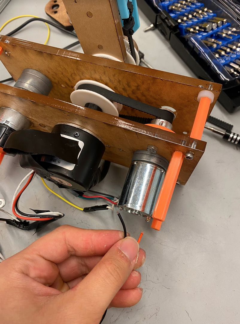
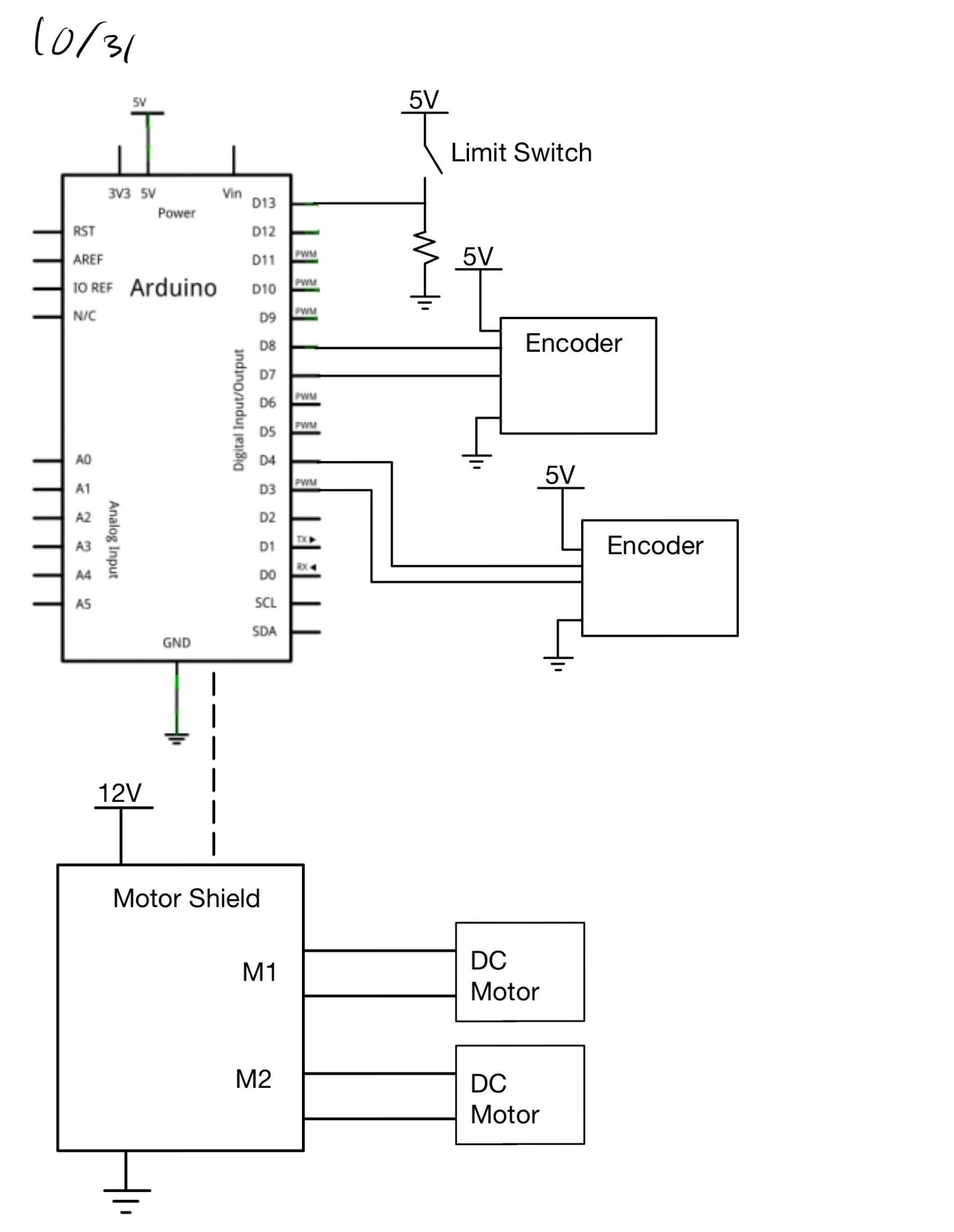
We used an Arduino to control our electrical system. However, because the Arduino itself cannot provide enough power to drive the motors, we added a motor shield connected to the Arduino as well as 12V power.
In order to have good control over the position of the steel ball within our sand enclosure, we needed to know the position of our two DC motors at all times. We decided the best way to do this would be to use encoders. Encoders are a type of sensor that can tell how much a shaft has rotated in terms of steps. By using the given number of steps per rotation of our encoders, we would be able to determine the distance and angle between the center and the position of the magnet. These encoders could be connected directly to digital pins on the Arduino.
Because encoders reset to zero when they are powered, we considered including a limit switch at the center of our enclosure so that we can determine where the zero position is even in the case of not starting in the center. However, this was not an issue we were encountering, and we decided to forgo actually adding one.
The goal of sprint one was mainly focused on getting our mechanical and electrical system into a place where we could start testing software. We did not have a complete control scheme by this time, but we were able to move the motors independently between encoder positions. We used Arduino’s encoder library to read encoder positions as the motors moved and stop them once the desired value was reached.
Exploring different methods of programming patterns into the motors.
The primary goal of the mechanical work in sprint 2 was to fix all of the sprint 1 mechanical bugs to allow effective software testing. We first addressed the bending axle by using a metal insert surrounded by a 3d printed cover:
In preparation for the final sprint, we purchased belts, hardware, and MDF.
The electrical design did not change significantly between our first two sprints. Our plan at the time was to continue using DC motors with encoders.
The main focus of this sprint was on the software. In further testing motor motion, we realized that when changing the angle of the arm, we also changed the magnet’s distance from the sensor because their belt pulleys shared an axle. We had to account for this in the inverse kinematics to determine the necessary motor angles based on the desired location of the magnet.
Our first plan to create patterns was to make a series of close-together points and move the ball between them. The concept worked theoretically, but we were having issues precisely controlling the position. Our motors were relatively fast, and even at the slowest setting we could manage without stalling, they frequently overshot the desired position by a significant number of encoder steps.
After realizing that it would be more difficult than expected to create patterns this way, we considered an alternate option of just controlling the speeds of the motors. This would create smoother and more continuous motion without worrying about the encoders but would restrict the kinds of patterns we could create. Using the speeds method, we were able to tune the speeds correctly to create a perfect circle.
Final mechanical design and switching to stepper motors.
For the final sprint, we designed and fabricated the final mechanical enclosure and motor mounting with material that we purchased. Using timing belts that were purchased and made to a custom length fixed the issue of timing belts breaking because of us gluing things together. We changed the mechanical design slightly to adapt to hold stepper motors instead of DC motors. We also made the sand enclosure to hold all of the sand with the ball by gluing and bolting together layers of MDF. The final large change was instead of having a belt that held the ball to control the axial motion, we changed it to being a second arm with the rotation point being the end of the first arm. Previously, the axial motion was limited because the belt couldn’t rotate completely, but this new design allowed us to go to any point without any constraints and use a continuous belt that has a much lower chance of breaking. This resulted in a fully functional and aesthetic mechanical design to allow electrical and software to create patterns in the sand.
Switching to stepper motors required changes to be made to the electrical design. At first, we had some difficulty determining how to run the motors. We started out trying to use the same motor shield but quickly realized this was not an option after burning it out. Next, we tried to use an L298N motor driver to control each motor. This had some success initially but stopped working at later steps. After extensive debugging, we determined that one of the drivers had broken somehow after our first attempt. Our final method of controlling these motors was with A4988 stepper drivers. These ended up being successful in driving the steppers without burning out.
Using the stepper motors eliminated our need for encoders since their position should already be known due to the nature of stepper motors.
Our final design included the addition of a strip of LEDs along the ends of the enclosure. These lights need to be powered with a 5V supply and controlled with a digital pin on an Arduino. To work on the LEDs and motors synchronously, we started controlling each on a different Arduino. In the end, there was no reason to consolidate to one device.
With the new motors and mechanical design, there were significant changes to be made to the code architecture. For one, we switched from using the encoder and dc motor libraries to using libraries for stepper motors. This meant that instead of running the motors until they reached a specified position, we could instead move them a certain number of steps for a similar and more accurate result.
Similar to our previous design, we needed to convert desired polar coordinates into motor positions. However, with the new design, we needed a different set of equations to perform the inverse kinematics, detailed in the software section. With desired angles computed, we use the number of steps per revolution to determine how far to step the motors.
We were able to go back to our original plan to make patterns using small motions between points. The only issue with this method is that the stepper motors do not create much torque. There is a lot of friction between the ball and the sand, so the motors sometimes miss steps. However, this has proved to be a manageable issue by slightly increasing our maximum distance to compensate. At the end of this final sprint, we are able to create patterns such as circles and spirals that move inward and out.
What we learned from this process.
In the beginning, we ran into a lot of issues with both parts breaking and interference issues. The issue with parts breaking was mainly because we were doing quick prototyping to give electrical and software a product to start testing with, but because things were breaking it was difficult for them to do real testing. The parts that broke were the timing belts and the shaft bending. We were gluing timing belts together for a while since we had to wait for the ordered continuous timing belts to arrive. In hindsight, it would’ve been better to order the timing belts first and design around the dimensions of the belts that we ordered, that we wouldn’t have to deal with the belts constantly breaking for the first prototype and this would’ve allowed electrical and software to get a lot more done in the beginning. The interference issues were due to not paying close attention to the CAD assembly, so we had to refabricate some parts later on.
Another thing we learned was that it’s easy to misjudge how long something will take. In some instances, we planned to have the mechanical side of things done by a certain deadline, but it would take a lot longer than expected so the entire timeline had to be pushed to accommodate. In the end, we learned that it’s better to allocate more time than expected, especially when fabricating and assembling.
One thing we learned was the importance of using the right parts for the job. We started out with DC motors with too much torque, so they overshot the target more frequently than not, making the encoders less helpful in determining position than we thought they would be. When we switched to using stepper motors, it became a lot easier from a software standpoint since they are more designed to move to specific positions. However, these motors had less torque than anticipated. The accuracy of their positions worsened when they started to lose steps combatting the friction of the ball against the sand. If we could redo this project, we would have specced out the right motors more thoroughly at the start.
In a similar vein, we had trouble finding the right drivers for our motors since it was a rushed switch. We burnt out two different types of boards before finding drivers that worked. This is another case where we would have benefited from deciding on the right parts earlier.
As a stretch goal, we initially hoped to have a web server that users could input their own patterns to for the sand table to draw. In the end, we ended up with only 3 different patterns: circles, spirals, and roses, without the web server.
One of the biggest takeaways from the software development in this project was that no matter how well the code works in theory, it needs to be adjusted to match the constraints of the mechanical and electrical system. For example, in the first two sprints when we were writing code to move the DC motors to certain points using the motor encoders, we found that the motors would overshoot the target position and end up oscillating back and forth even as it attempted to draw a very simple pattern like a circle. Although our algorithm for moving the motors to the right positions was correct, we had to adjust the motor speeds and angle step size because the motors we were using could not handle accuracy when there was abrupt acceleration.