Mechanical Design
Keyboard
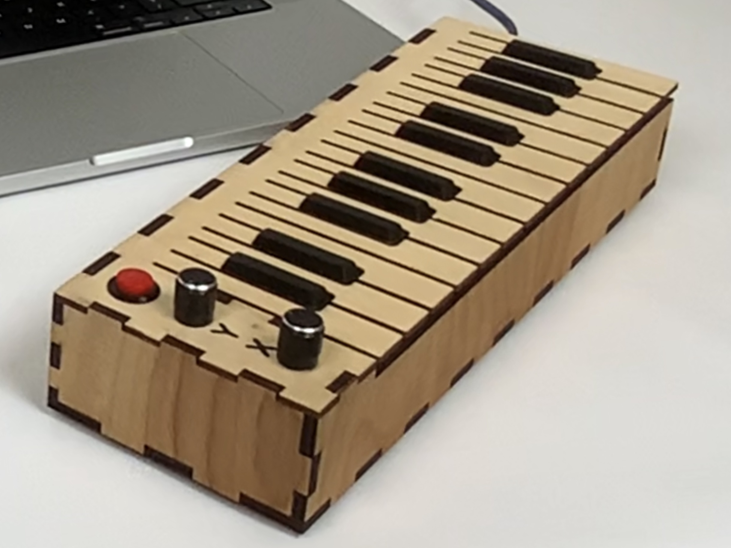
The integrated mechanical aspect of this synthesizer is the keyboard. A piano keyboard can come in many shapes and sizes and be made using a wide variety of different mechanism types. We focused on creating a striking appearance that is also functional, easy to assemble, and durable.
The final keyboard serves as the enclosure for the Arduino and houses the piano keyboard itself, two knobs for the etch-a-sketch function, a button to erase the screen, and an input for a sustain pedal.
The keyboard is constructed from laser-cut 1/4in and 1/8in plywood. It is assembled with finger joints and wood glue. The bottom plate screws into 3D printed brackets for easy servicing. 3D printed black key caps are used to make the keyboard familiar to the touch and easy for a musician to play.
The switch arrangement for the keyboard is deceptively simple. Each key is a flexible finger sticking out of the top plate. Under each key is a tactile switch, the same kind used on a breadboard. Arranged this way, the keys have a satisfying click, and they are durable and easy to assemble.
Overall, this was a fun, creative mechanical design to work on, and it brings a sense of substance to our project.
The .DXF files and CAD we used to produce the keyboard can be found here:
Laser Projector
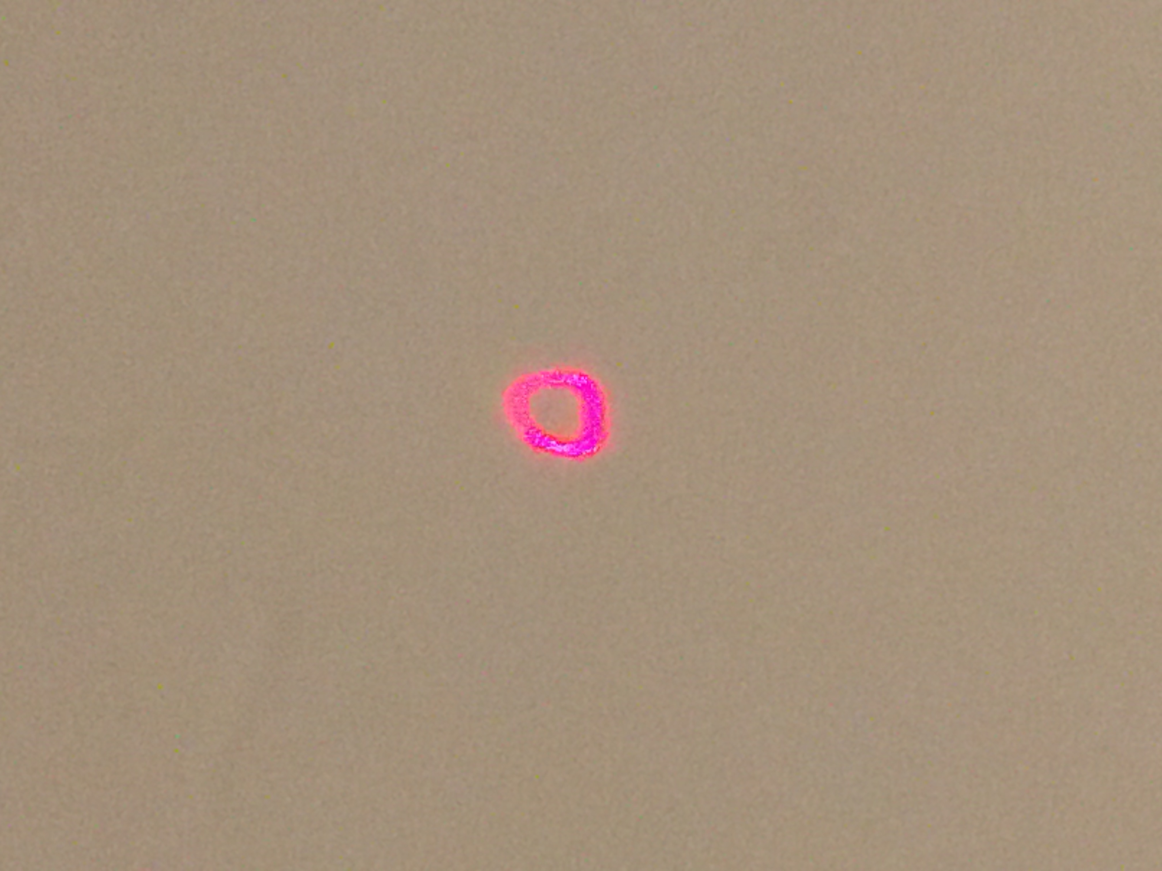
The original mechanical ambition of this project was a laser projector, also known as a laser galvanometer or galvo. The general concept is that a mirror can be moved in two axes, and if a laser is bounced off the mirror, the movement can move the laser beam to trace out graphics. This is the exact same concept used by oscilloscope music, and we hoped to play oscilloscope music through a laser galvanometer to project the figures contained in the music.
Laser galvos generally work in a very similar way to speakers. Both use a voice coil to create movement. A voice coil is a coil of wire placed near a magnet. When current is run through the coil, it generates a force relative to the magnetic field. If you attach the coil to a mirror and fix the magnet to the base, the mirror will move.
Prototype 1: Sketch Model
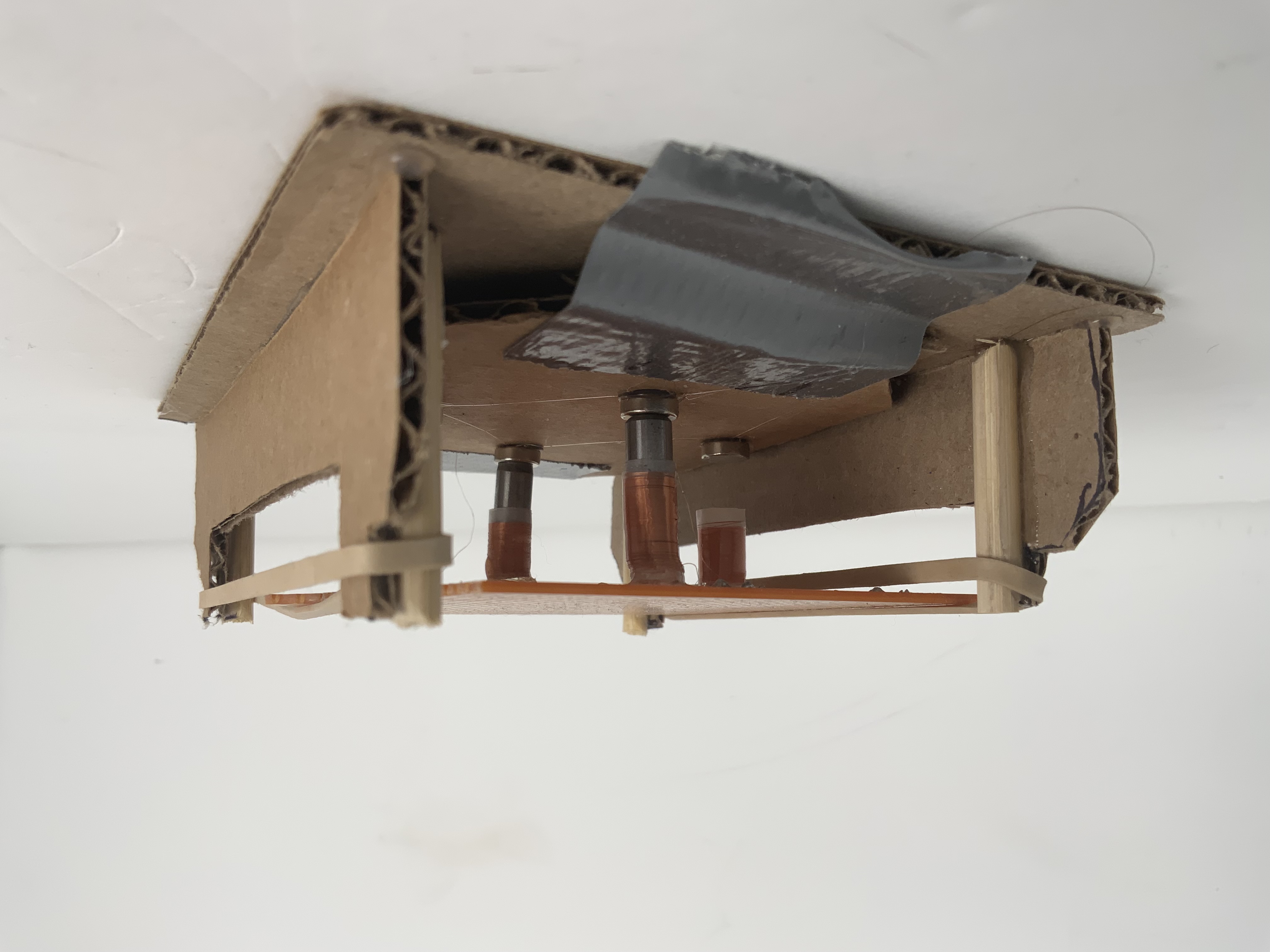
The first prototype of this concept was very simple. It was a piece of circuit board with four voice coils mounted on the bottom. It was suspended by rubber bands over four corresponding magnets. The coils were wired in two opposing pairs such that one pair controlled the horizontal axis and the other controlled the vertical. The two coils in each pair were wired in opposite directions so that one pulls up while the other pushes down. This caused the platform to tilt. A piece of adhesive mirror was added to the platform and a laser bounced off. This prototype suffered primarily from inefficiency in the coils. The magnets used were very poor, so they mostly heated up rather than provide force.
Prototype 2: Spiral Suspension
The next prototype was very similar, but used a 3D-printed suspension and larger, neodymium magnets. This platform suffered from issues with the suspension design, which was compliant in vertical movement but very stiff in tilt, and didn’t allow for significant movement of the mirror. We also found from this platform that the tilting is much more effective when the coils are above the magnets rather than around them. When the coil is around the magnet, it tends to rub and bind because of the tilting.
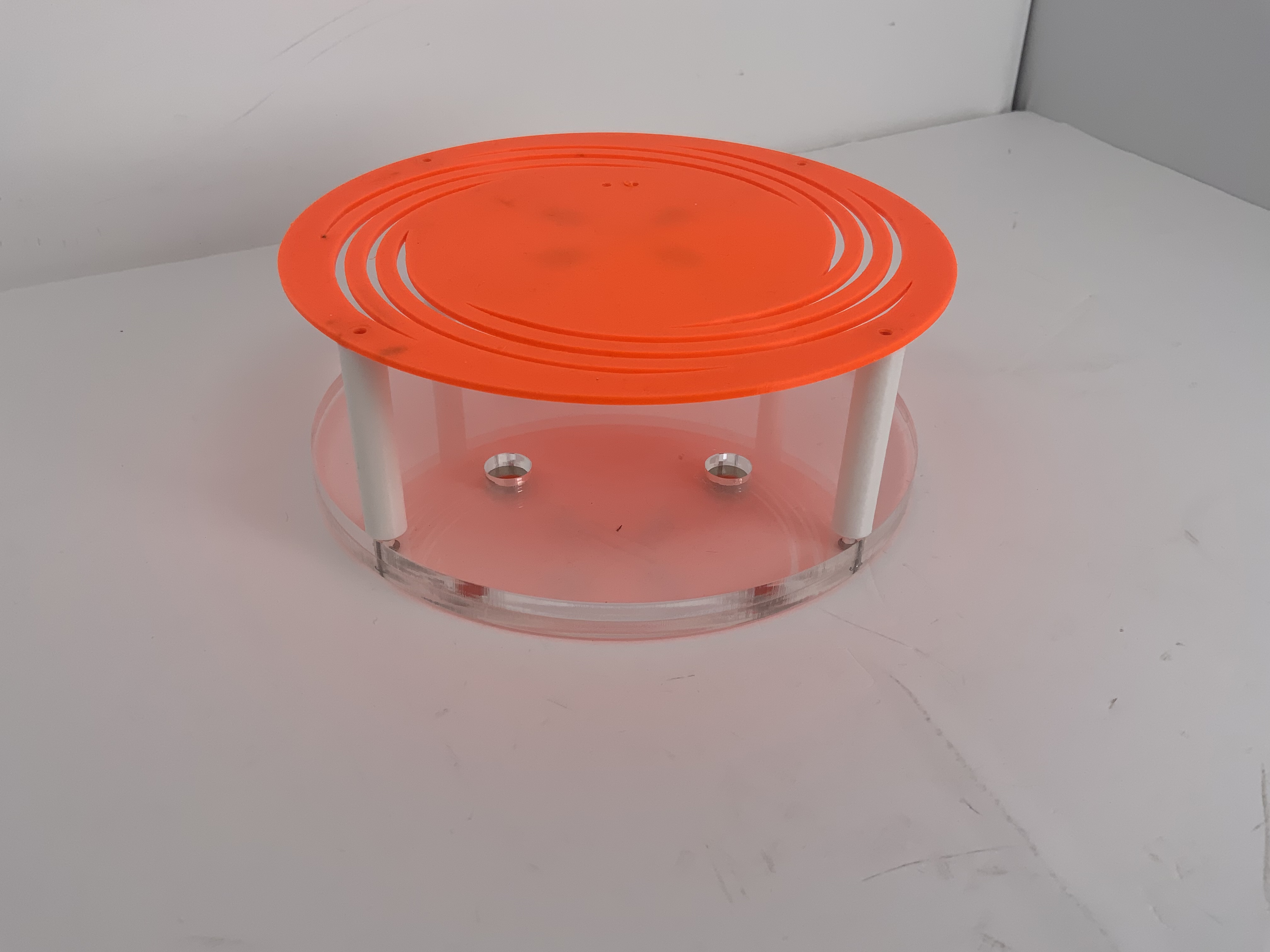
Prototype 3: Gimbal Suspension
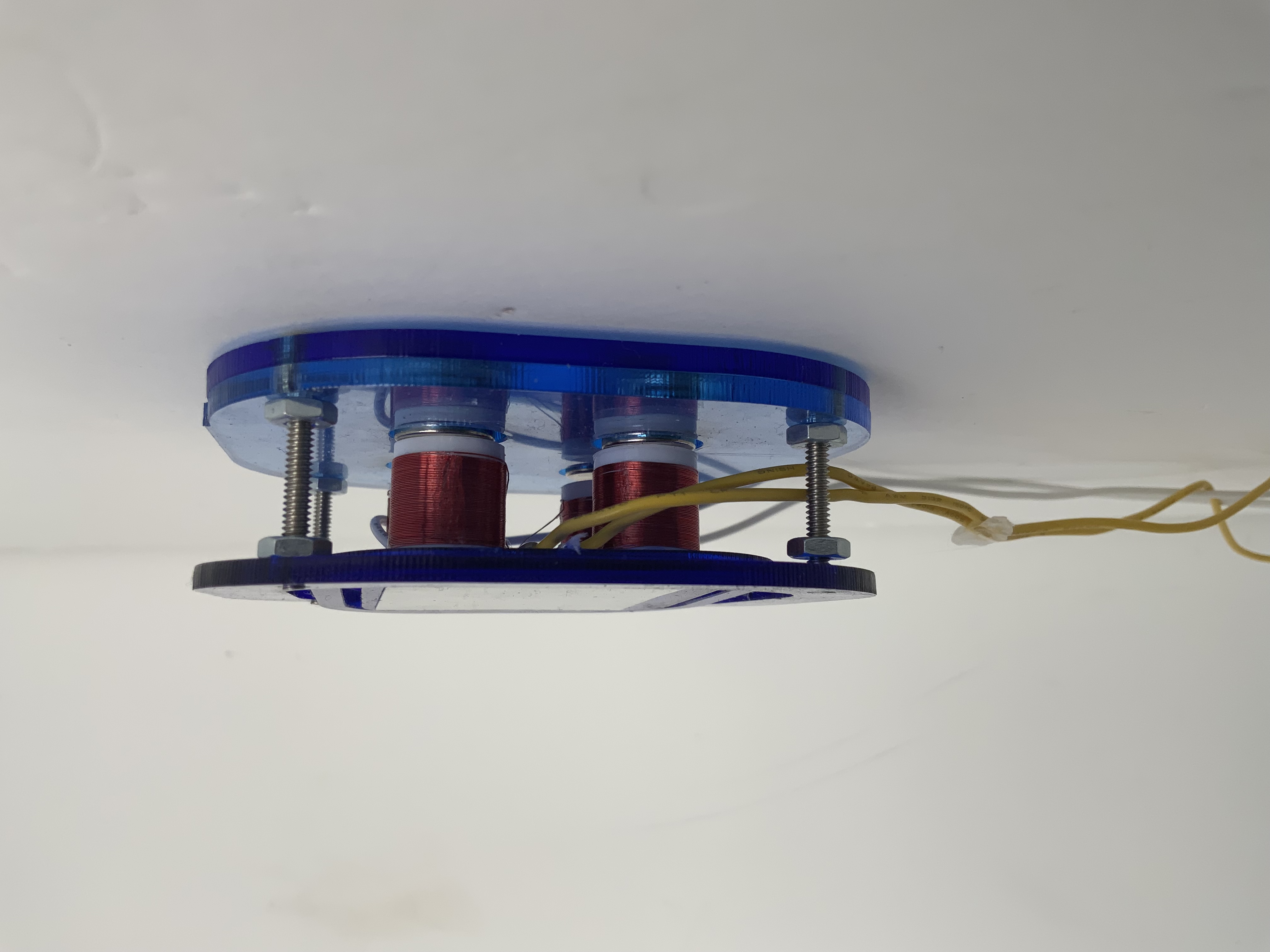
The next platform used a different, gimbal-style suspension system. Each axis had a joint that was compliant in rotation, but not in translation. This allowed the platform to tilt, but not move up and down. It was also much smaller because of the altered coil design. When the coils are above the magnets, not nearly as much clearance is required between the magnets. This platform worked well, although it suffered from what we believe to be coupling between the two axes. They weren’t operating completely independently, so trying to draw straight lines was almost impossible because of the wobbling of the platform.
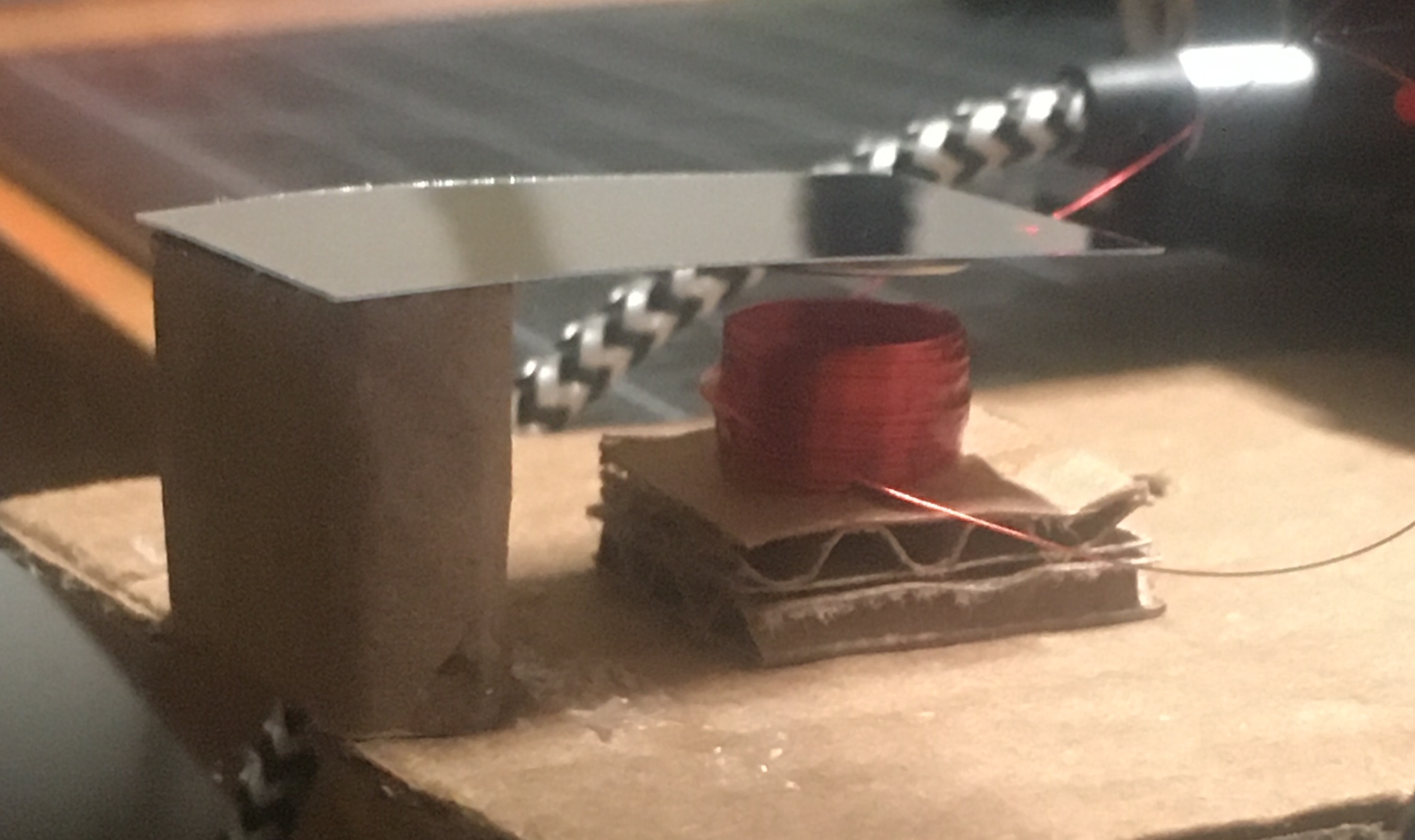
Prototype 4: Flappy Mirror
This realization caused us to pursue separate axes each using its own mirror. This is more similar to how commercial laser projectors work. We tried attaching a magnet to a “tongue” of mirror film and suspending that over a magnet. This was very light and seemed to work, but the coil would overheat when enough power was delivered to significantly deflect the beam.
Prototype 5: Motors
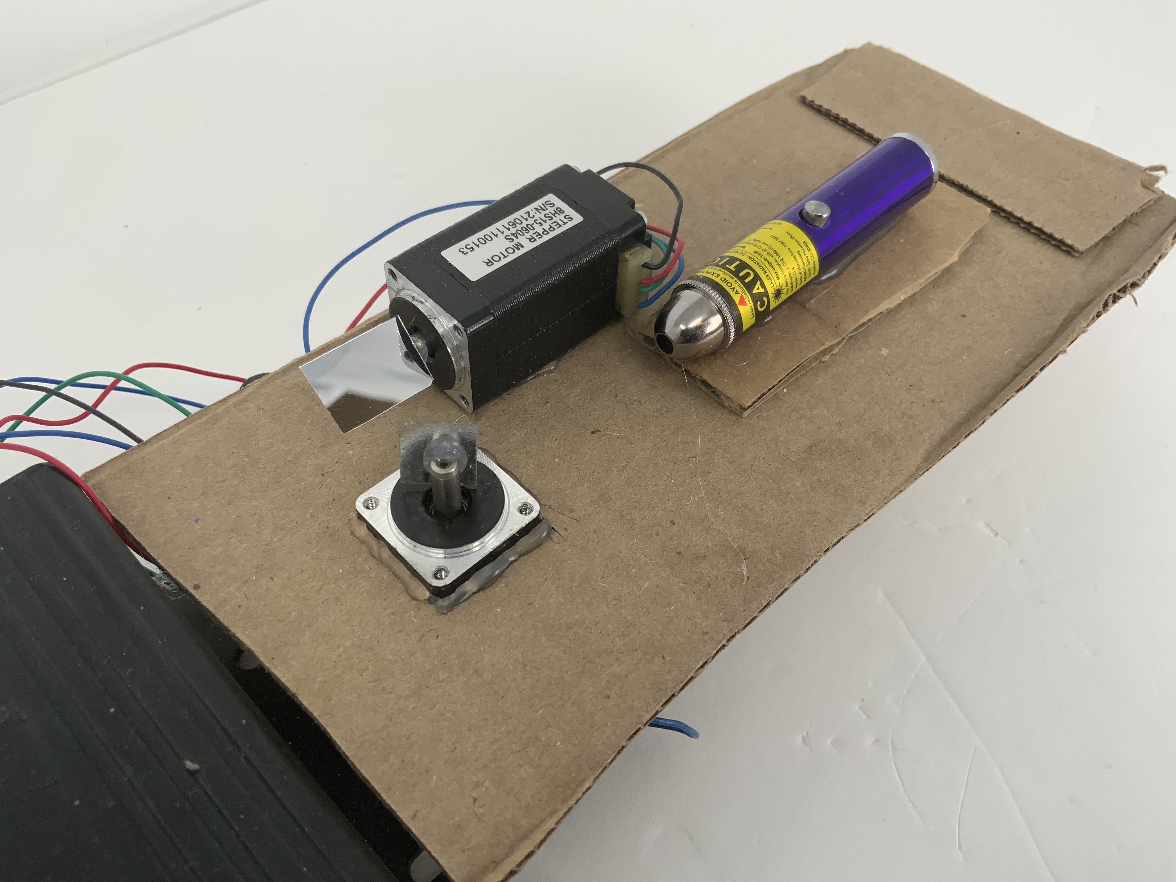
For the time being, we decided to investigate using off-the-shelf motors as rotary galvos. We connected brushless and brushed DC motors, as well as a stepper motor, to our audio amplifier. Of these, the stepper motors delivered the best performance.
All of the motor types, not being purpose-built galvos, have a tendency to start rotating at higher powers, therefore they can only be run with very small movements. That said, we selected the stepper motors for our final galvo prototype.
Conclusion: Physics 1, PIE Team 0
It was at this point that we came to the realization that no galvo design we would be able to construct, even commercially produced ones, would be capable of reproducing the very high frequencies present in oscilloscope music. For this reason, we decided to use the stepper galvo as a separate proof of concept, and put our mechanical focus into the keyboard instead, since the galvo would be unable to operate at frequencies that would be considered musical.