
Anna Braun
Mechanical Engineering
A modernized take on the Enigma M3 Machine used in WWII to encrypt and decrypt messages.
built by:
Anna Braun,
Jo Walkup,
Kuhu Jayaswal,
Leo Trepte,
Tchenzie Guichette
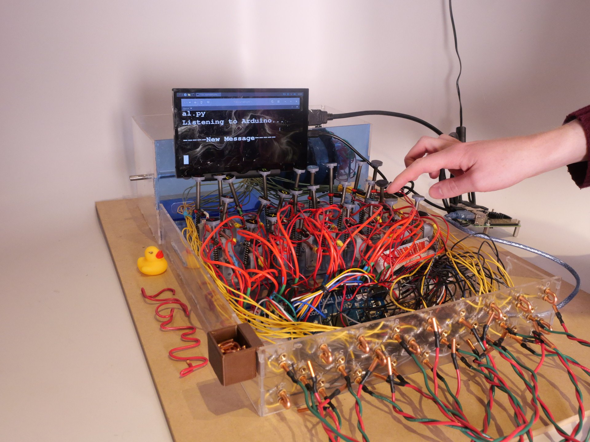
An electro-mechanical project developed by a team of five Olin College students for Principles of Integrated Engineering (PIE) course of Fall 2025. In the demo below, the message "PIE" was typed using a specific configuration. When the encrypted message "WOD" was entered back using the same settings, the screen output our original message. This demonstrates a successful run of our Enigma replica.
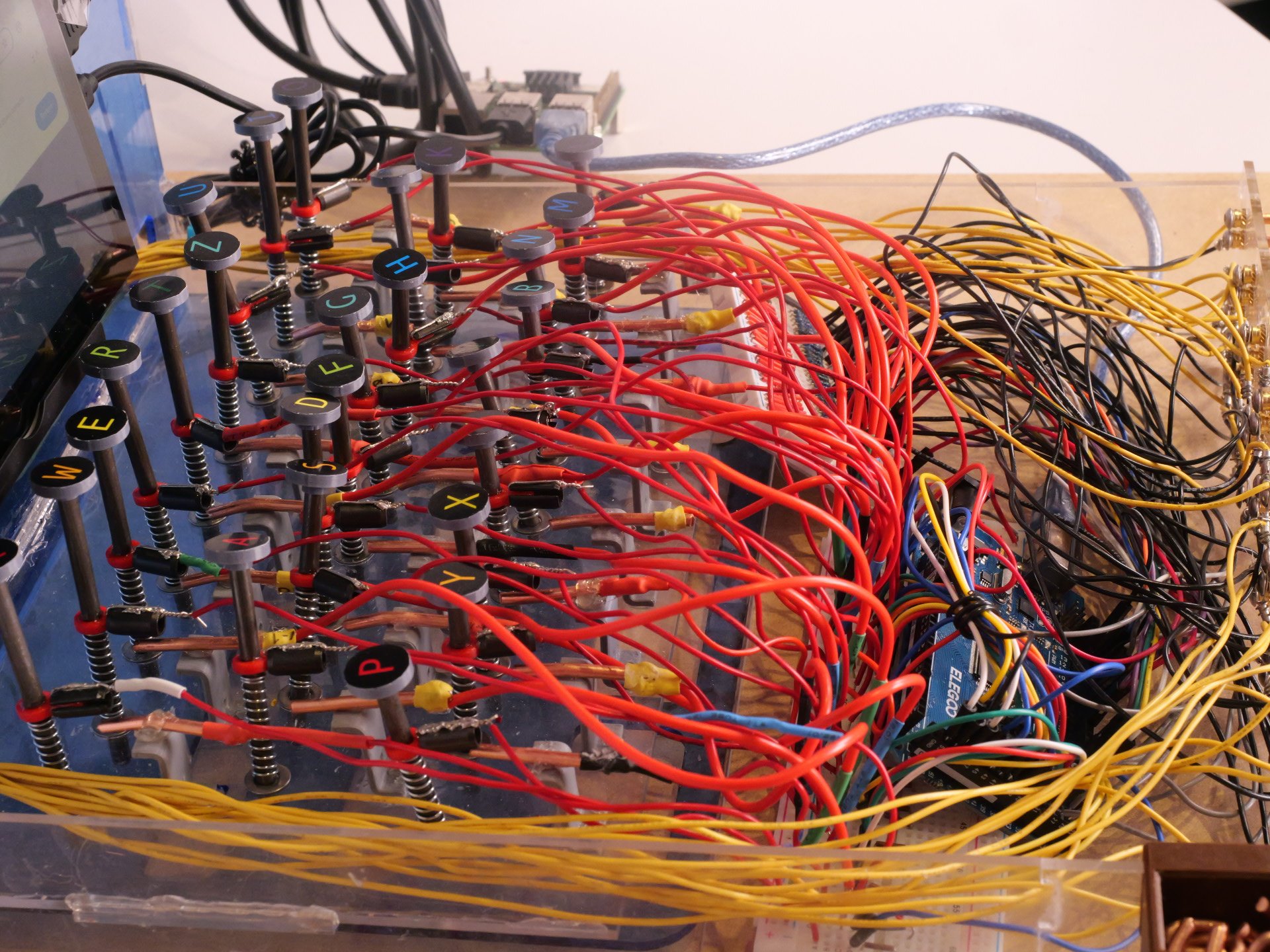
The keyboard design borrows from the original Enigma Machine. It uses spring-loaded metal rods topped with labeled key-caps. When a letter is pressed, the key completes a circuit on the breadboard which gets sent to the Arduino for processing.
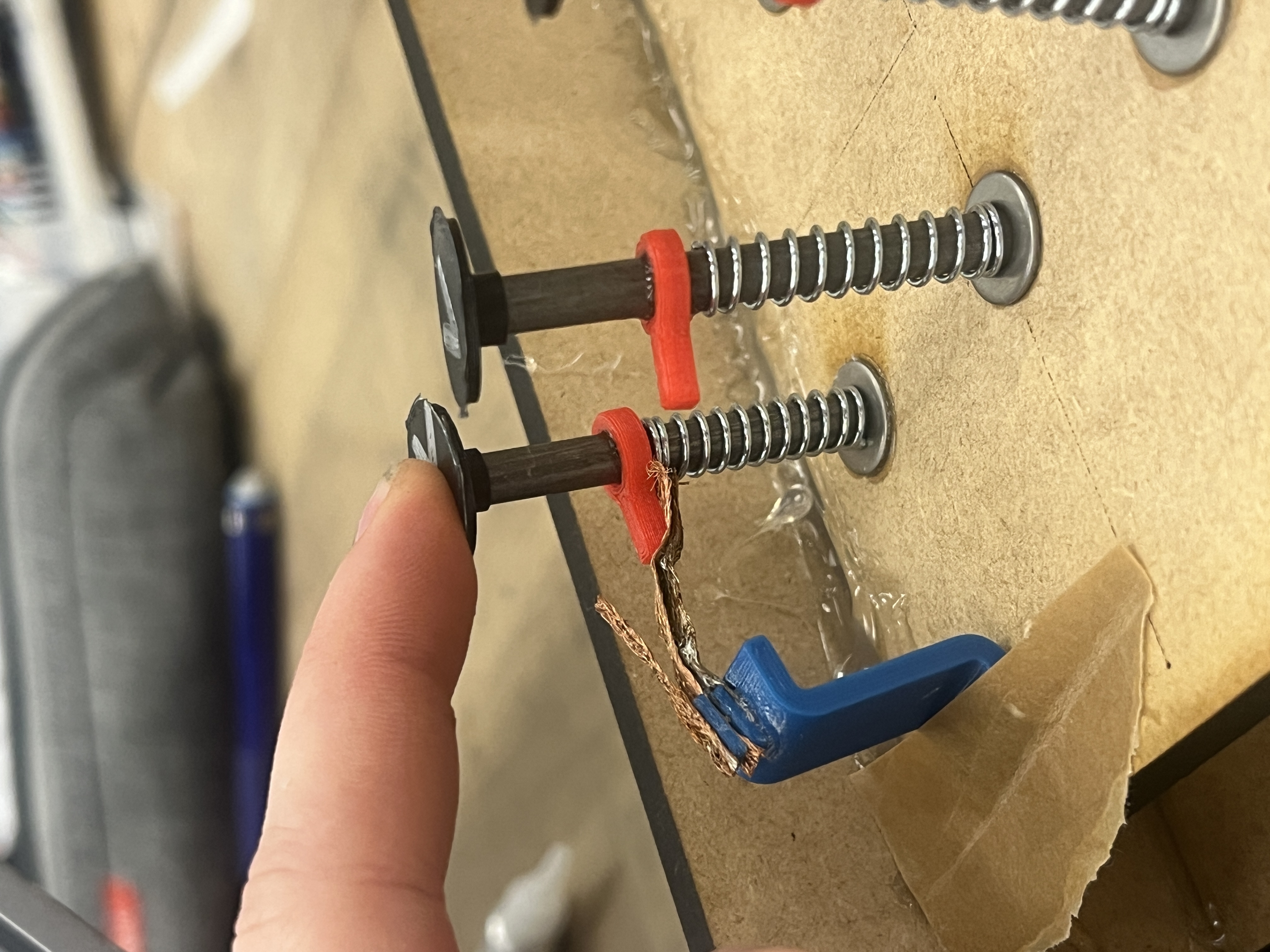
The original idea was to use a small length of solder wick because it was conductive and flexible. However, since solder wick oxidizes so quickly, it might become unreliable, which led us to look for more reliable solutions. We decided to use copper wire and split bushings instead.
The first iteration we had originally had the copper pieces sticking out from the brackets at an angle. It became clear that this wouldn't work as the springs were too stiff and required too much force to contact well. Instead of redesigning, which would have taken too much time and iteration at that stage of the process, we just glued the copper pieces on top of the brackets, as they were at a good height.
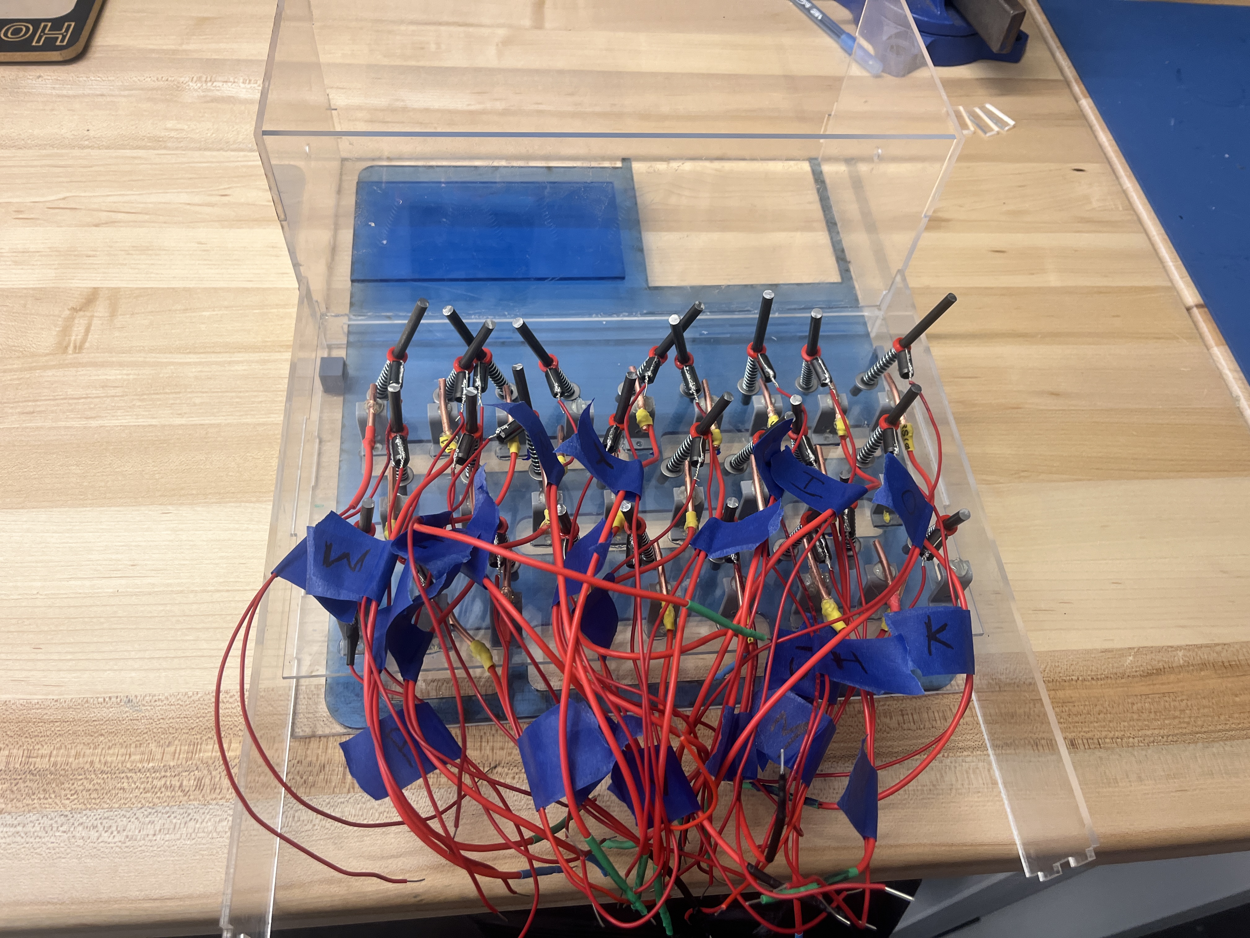
A compromise we had to make was not using a lid. We had designed and laser-cut a lid, but with the amount of wires we had, and the non-constant key height, the lid would not fit. If we did this project again, we would have designed to be able to have a lid, which would restrain the keys from wobbling as much as they did.
A tradeoff to making the keyboard as opposed to using a standard keyboard is time and redundancy. Since keys are made using springs and many small parts, each key is essentially a small mechanism, requiring hours of soldering. Since there are 26 letters in the alphabet, this creates long-repetitive tasks for the assembly of dozens of parts.
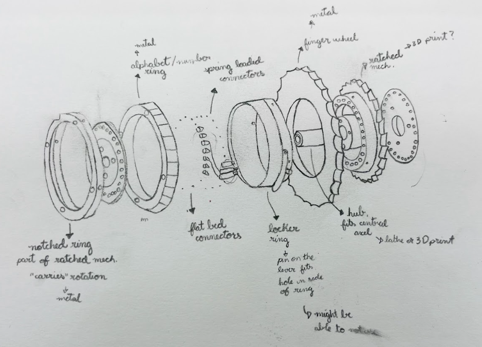
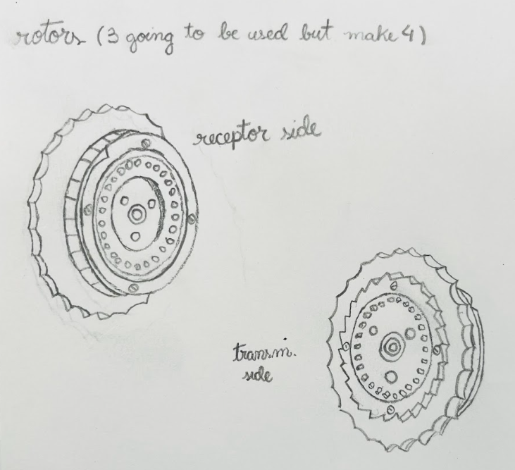
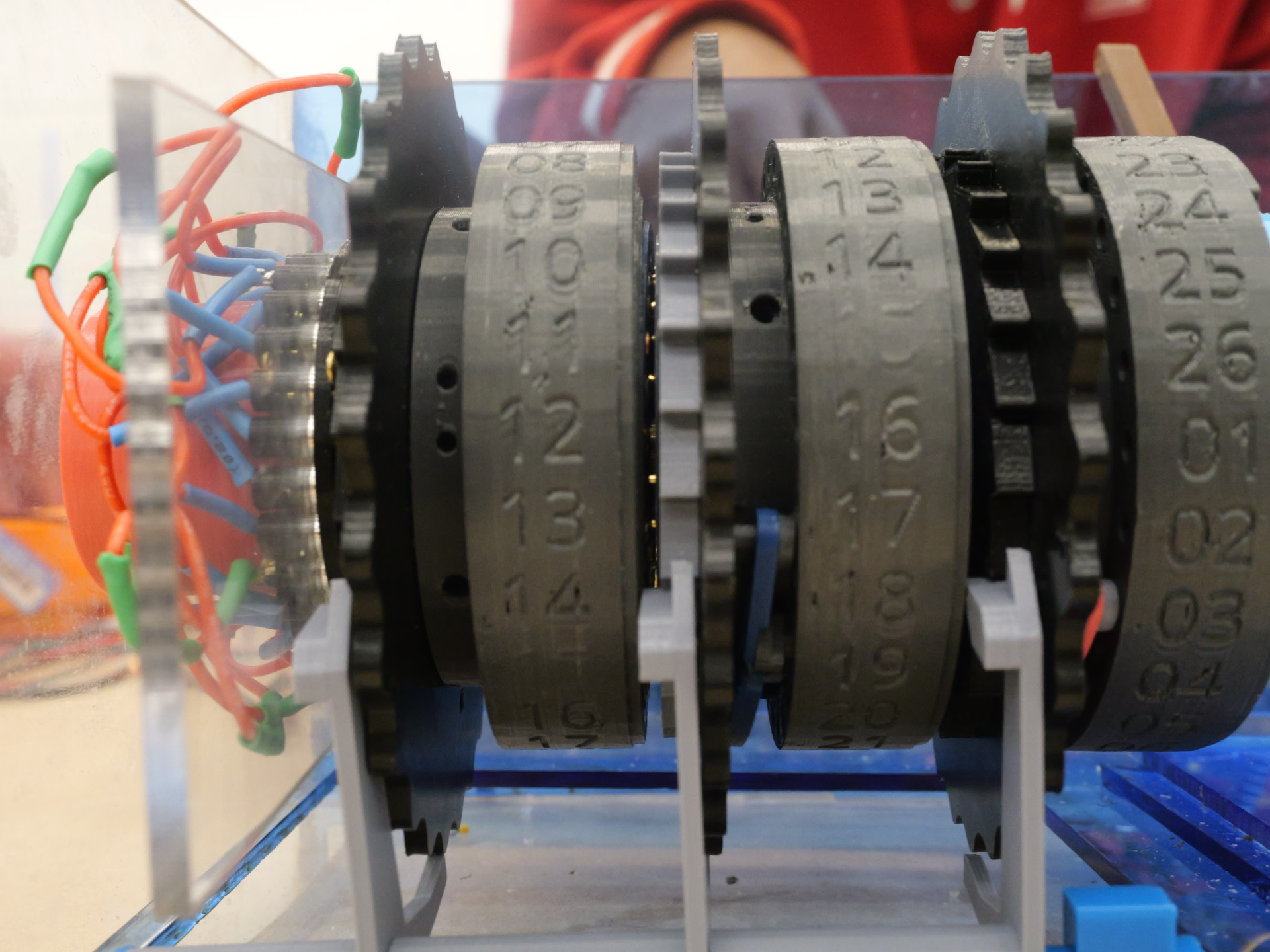
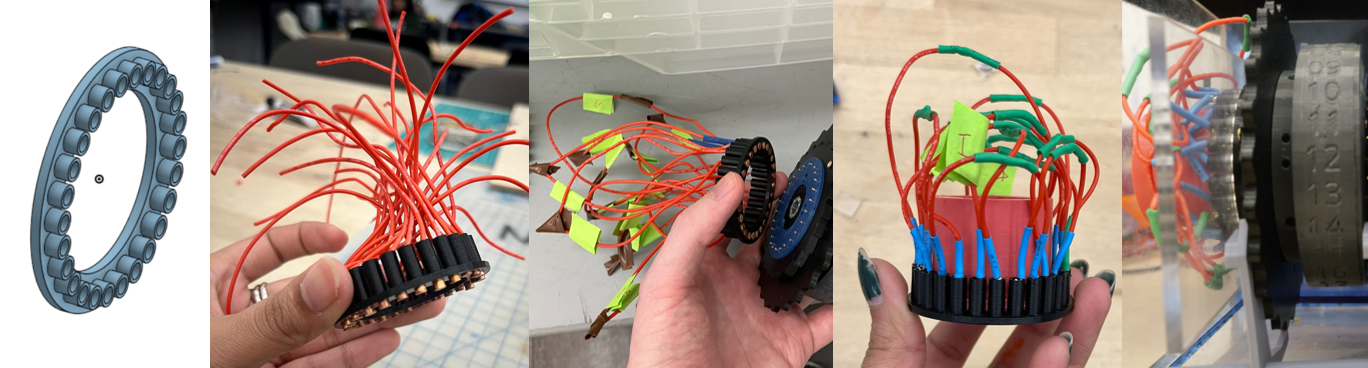
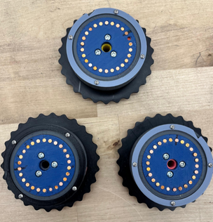
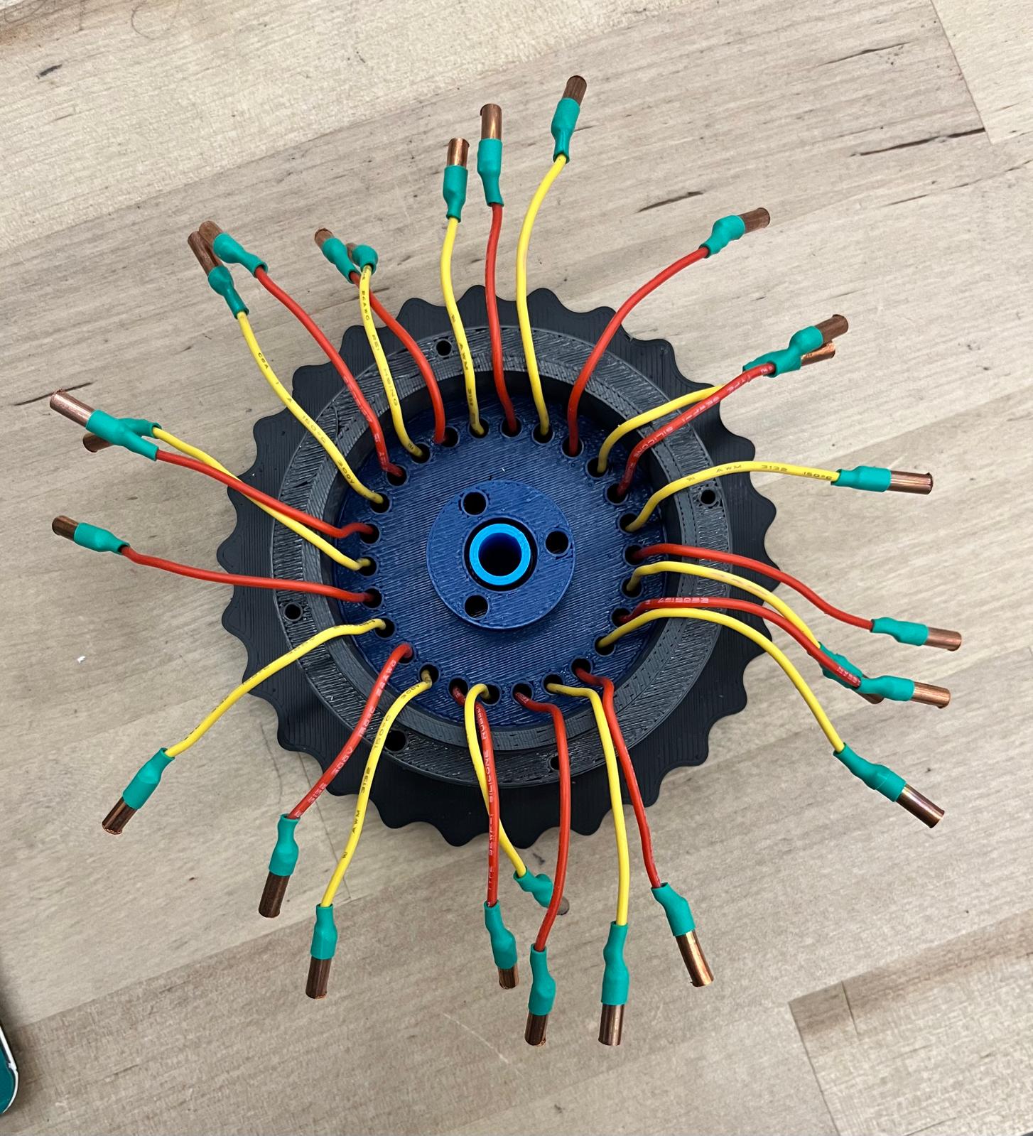
The rotor assembly is the core electromechanical subsystem of the Enigma Machine, responsible for performing the encryption logic. As the signal travels through the three rotors to the reflector and back, each rotor remaps the input through its internal wiring, resulting in six successive letter substitutions. Electrically, the signal enters each rotor through recipient pins, is redirected by the internally scrambled wiring, and leaves through spring-pin contacts to the next rotor. After reaching the reflector, the signal returns through a different path, generating a second set of substitutions.
The design was based on the original Enigma rotor architecture, but as development progressed, it evolved through multiple practical adaptations and original design decisions driven by fabrication methods, mechanical constraints, available components, and the project timeline.
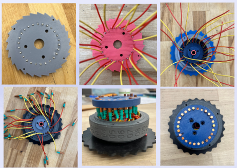
One of the first major adaptations was scaling the rotors. Early prototypes allowed only approximately 4 mm of space for internal wiring, which proved insufficient for reliable soldering, routing, and alignment. Increasing this space to approximately 2 cm enabled clean internal wiring, improved rotor alignment, and stable integration of spring-pin contacts within our manufacturing capabilities.
Material selection for the recipient pins was also influenced by availability. Aluminum pins were initially considered because they were readily accessible in the shop, making them a practical early choice. However, aluminum forms an oxide layer that prevents reliable soldering without specialized fluorine-based flux. To avoid this limitation and improve electrical reliability, we transitioned to 8 AWG copper wire. The pins were fabricated by cutting the wire to length and flattening the ends with a belt sander to create smooth, consistent contact surfaces.
The assembly process evolved alongside the design. An initial assembly sequence proved impractical due to alignment issues when installing the ratchet wheel. This led to the development of a revised method that prioritized mechanical alignment before final wiring. All 26 spring pins were first locked between the ratchet wheel and locking plate, after which wires were soldered, routed, and terminated with copper pellets and heat shrink. The wires were then scrambled according to the rotor key and enclosed within the copper housing, which was secured using three M4 screws.
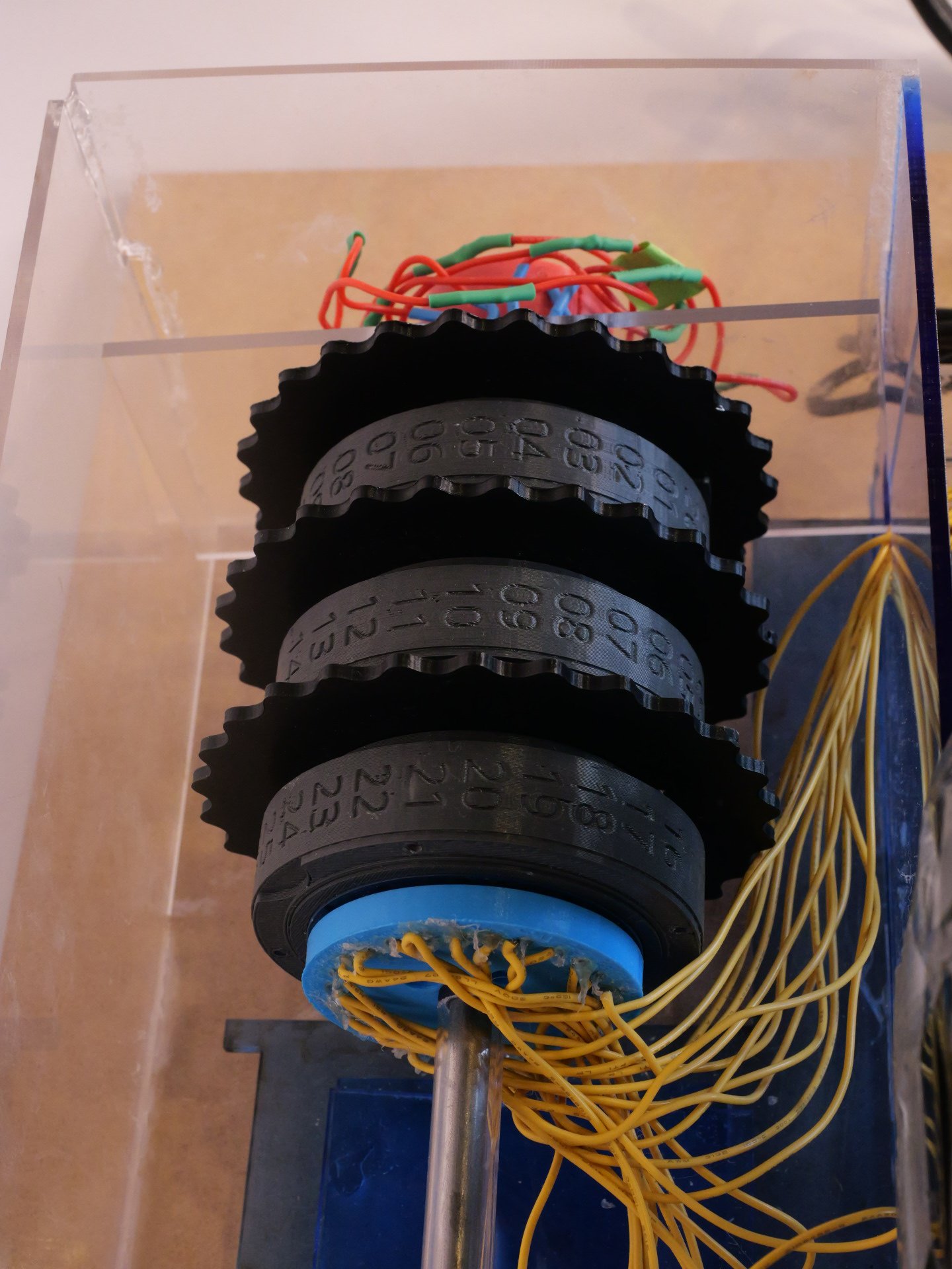
For rotor motion, we attempted to replicate the original seesaw-driven ratchet stepping mechanism. A thick driver actuated a seesaw assembly made from acrylic and 3D-printed components, converting linear motion into discrete angular rotation of the ratchet wheel. The geometry of the ratchet teeth and notched plate was redesigned to match the enlarged rotor size and pin spacing. During testing, however, we found that reliable electrical contact required greater spring-pin compression than the seesaw mechanism could provide. As a result, automatic stepping was not dependable in this iteration. To ensure consistent operation, rotor rotation was implemented manually using integrated thumb wheels, preserving functional behavior while improving reliability.
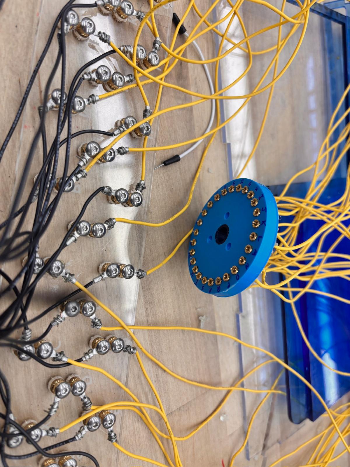
The reflector receives the signal from the rotors and sends it back through a different rotor pin. To design the reflector, we went through an iteration to align the spacing of the reflector pins with the rotor pins and ensure a press-fit that was strong enough that the pins would not slide back when compressed, but were still able to be inserted. One change we made to the wiring was shortening the wires for a cleaner look and lower risk of them getting caught/snagged. The solder connections between pins occasionally broke. From this, we learned to solder the pins so that the solder did not interfere with the press-fit while keeping a strong connection, and added shrink-wrap to prevent shorting.
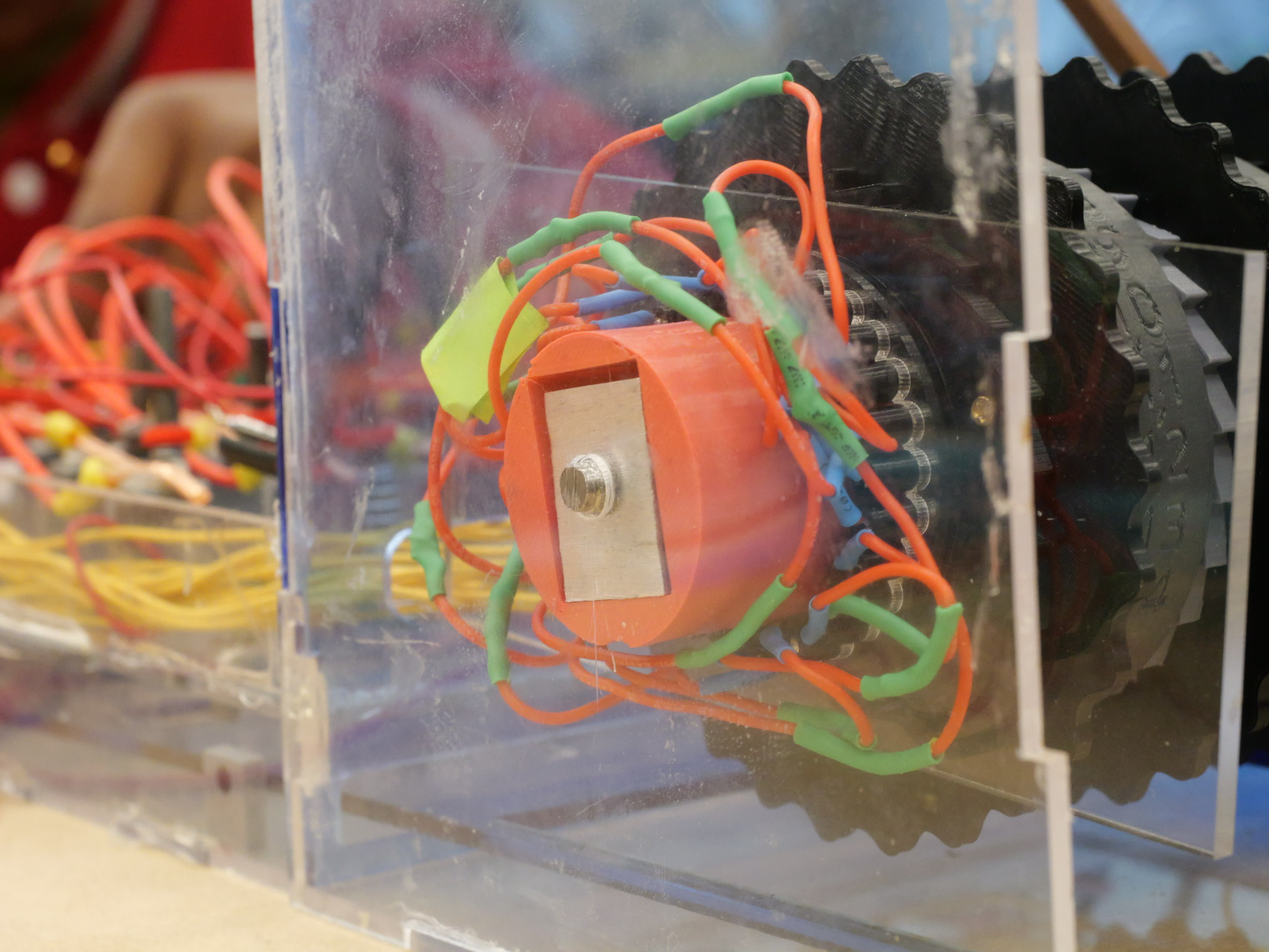
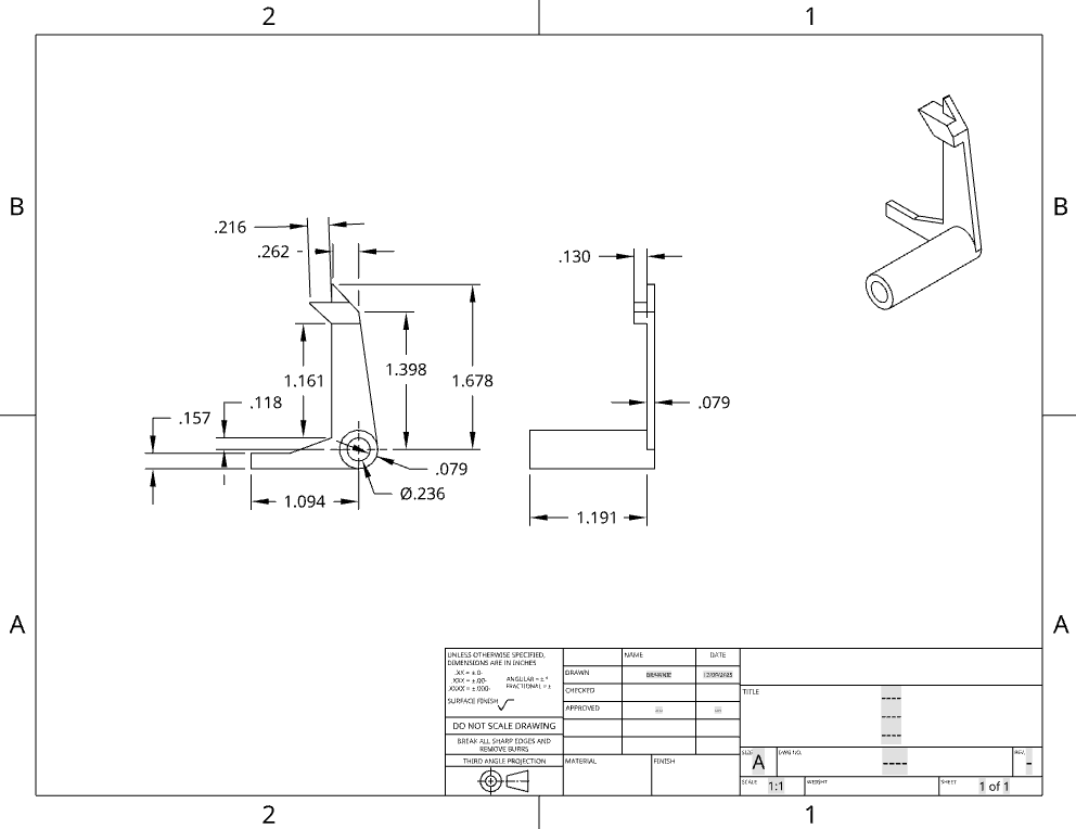
The compressor is composed of three parts: The 3D printed housing, an aluminum nut, the threaded end of our axle, and an acrylic rectangle. The housing slides into the reflector, applying force on it and the rotors. The housing has a hole that was made to fit the nut inside. The nut was made from a ~1in block of aluminum from a free scrap bin. We decided to make the nut because m7 threaded nuts were not available in the shop and we wanted to practice machining. We cut off a ¼ inch thick rectangle with a bandsaw. The hole in the center was made with a drill-press, then threaded with an m7 tap to match the 7mm shaft. Instead of cutting it down to be hexagonal, we made a cavity in the 3d printed insert that matched the shape of the piece of aluminum we found. The end of the device's main shaft was threaded with an m7 die. About an inch and a half of the shaft was threaded so that when the nut is on the shaft, enough shaft sticks out to go through the hole in the casing that holds up and aligns the shaft.
We wanted our plugboard to be an accurate representation of the real Enigma Machine, but with a few modernized twists. We decided that all swapping and encryption must be done physically through hardware, while the encrypted message would be displayed on a screen. We made this decision for a few reasons:
One trade-off that came with this decision was a delay due to ideation. Since the original machine did not include an Arduino, Raspberry Pi, or display, we needed to determine which new components to use, how data would flow between them, and how the modern additions would integrate with the original design.
For the first sprint, we got all of the CAD done. We also were able to produce a prototype of one rotor, as well as purchasing materials and getting started on the keys.
By the end of the second sprint, we had a prototype keyboard, a plan for the plugboard, modified parts for the rotors, and had created one finalized rotor. We also were halfway done with the reflector.
For the third sprint review, we had completed the individual keyboard parts, laser-cut the case, CADed the plugboard, and finished all the rotors. We also designed the ratchet system.
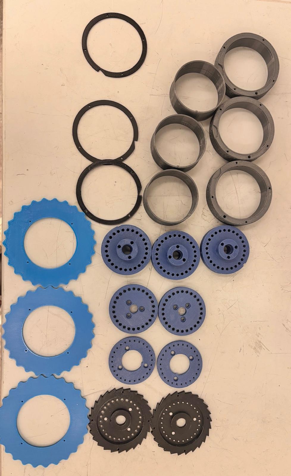
Each rotor is a nine-part mechanical assembly that rotates as a single unit to maintain precise alignment of the electrical contact pins. The rotor body acts as the main structural element, concentrically locating all components along the axis. A toleranced bushing between the shaft and rotor body reduces friction while ensuring accurate alignment during rotation.
All parts were dimensioned and toleranced for FDM Stratasys printing to ensure consistent fits across assemblies. Press fits are used where alignment is critical, while threaded fasteners allow disassembly and adjustment where needed.
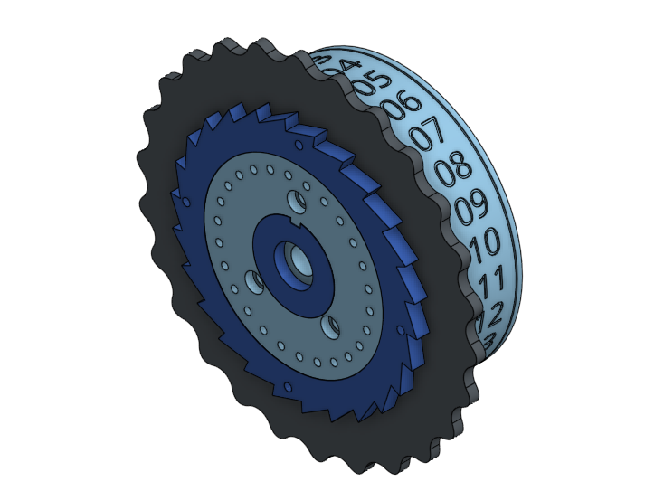
Indexed rotation is achieved through a ratchet wheel mounted at one end of the rotor body. The ratchet defines the angular step size and interfaces with the stepping mechanism. Together with the locking plate, it also radially and axially constrains the spring pins, keeping them aligned during rotation.
Rotor stepping follows Enigma logic: the first rotor advances every key press, the second once every 26 rotations of the first, and the third once every 26 rotations of the second. This behavior is enforced by a notched plate fixed to each rotor with M2 screws, physically preventing downstream rotors from rotating until an upstream rotor completes a full cycle.
The number wheel displays the current rotor position and uses friction fits with a small locking feature to prevent accidental movement. The thumb wheel allows manual adjustment and is mechanically linked to the ratchet wheel using friction and wood screws to guarantee alignment.
Internally, a routing piece connects to the ratchet wheel and preserves approximately 2 cm of space for wire scrambling. The copper pin housing supports the fixed copper pins and encloses the wiring, fastening to the routing piece with M4 screws to form a rigid structure.
Future iterations will focus on improving stepping consistency and electrical contact reliability, including lower-force spring pins and servo-driven rotor control, while preserving the original encryption behavior.


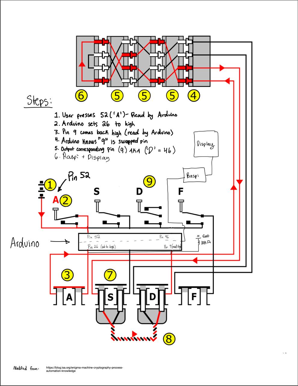
The keyboard design borrows from the original Enigma Machine. It uses spring-loaded metal rods topped with labeled key-caps. In our machine, when a letter is pressed, the key press completes a circuit on the breadboard, which is then sent to the Arduino. We chose to route keypresses to the Arduino for a specific reason: when the Arduino receives a signal for the swapped letter, both the pin corresponding to the keypress and the pin corresponding to the swapped letter will read high. By sending the keyboard press to the Arduino first, it can differentiate between the two, allowing it to send the swapped letter—and not the keypress—to the display.
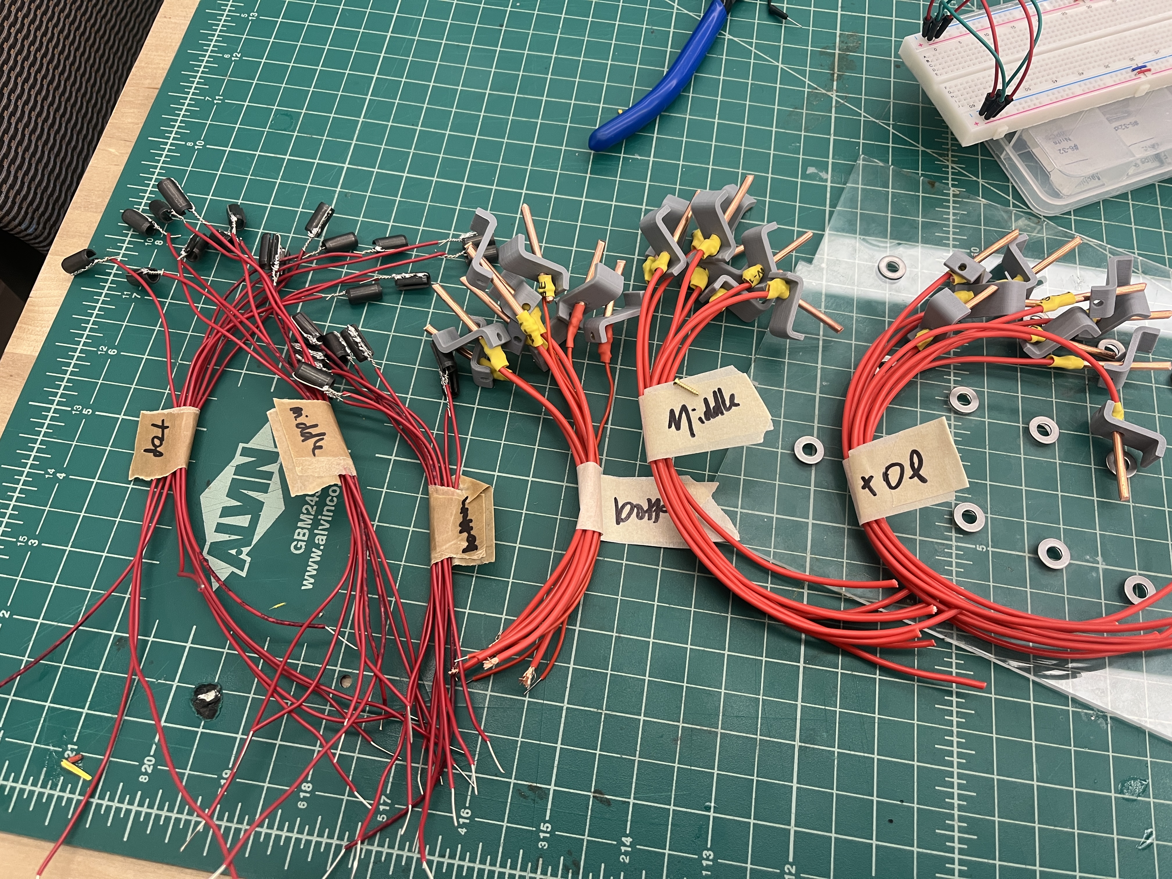
For the body of the key, we purchased a 6-foot length of cold-worked steel with a diameter of 3/16 inches and cut it to length using a horizontal bandsaw. We selected springs with a length of 1 inch and an inner diameter of 0.192 inches to fit around the steel rods. The tabs, keycaps, and brackets were 3D printed in PLA.
For the switch mechanism, we used thick copper wire soldered to 16-gauge or 22-gauge wire for one side of the switch. The other side was constructed using small split bushings soldered to 16-gauge wire. For the keycaps, we applied vinyl stickers labeled with the corresponding letters.
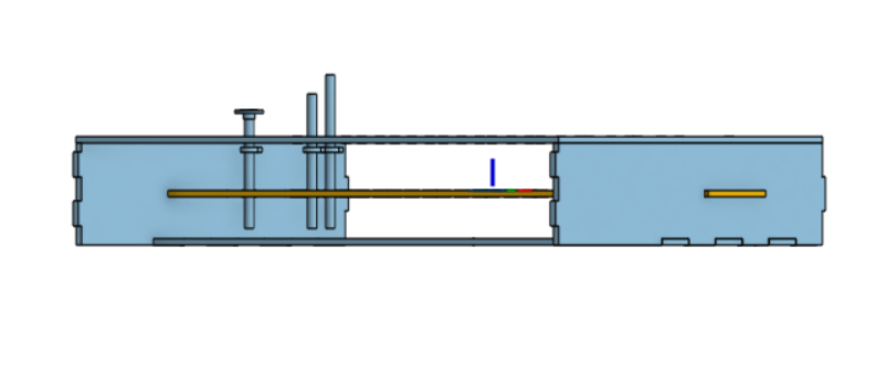
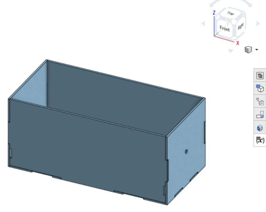
The case was designed early on in the process. This allowed it to evolve as we designed the internal components. We used parametric CAD in Onshape with variables for length, width, height, and wall thickness to facilitate iterations. Additional features like slots for keyboard integration and the ratchet system were added as needed. Once the design was nearly final, tolerances for laser cutter kerf were applied, and the acrylic pieces were assembled using solvent welding.
In the final build, one wall had minor fit issues due to a slightly misaligned reflector plate. We chose not to disassemble and fix it at that stage since the system was functional. Future iterations would address this, as well as tightening the shaft hole tolerance to account for threading reducing the shaft diameter.
The electrical components of the keyboard essentially make a button. There is a copper wire on a bracket, which in its resting position does not touch a split bushing on the actual key. When the two come in contact, they complete a circuit, and a signal is sent to the Arduino.
The electrical operation of the rotor system begins when a key is pressed, at which point the input signal is either swapped with another letter or left unchanged by the plugboard. The signal then travels sequentially through the three rotors, where each rotor applies a substitution based on its internal wiring and current position. After passing through the third rotor, the signal reaches the reflector, which redirects it back through the same three rotors in the reverse direction, causing the signal to be transformed again. In total, the signal is altered seven times: once at the plugboard, three times through the forward rotor path, once at the reflector, and three times through the reverse rotor path. Finally, the signal returns to the plugboard, where it is either left unchanged or swapped one last time before producing the output letter.
Without any plugs, the plugboard initially connects each letter's input to the output (ex. If the plugboard receives an input ‘A’, the plugboard outputs ‘A' to the rotors. By adding a plug and swapping two letters, one letter’s input becomes another letter's output. This changes the circuit. That letter will always come out as the swapped letter unless the plug is removed.)

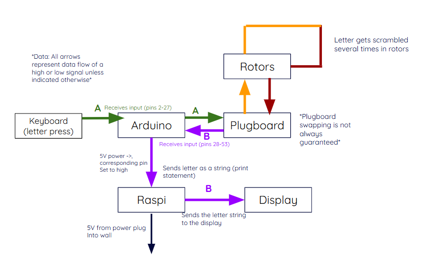
The following software includes 3 parts. The code for the Arduino which takes in a letter and outputs the corresponding pin (as demonstrated in the system diagram). The Raspi code uses a simple setup that listens for the output from the Arduino through its serial port and outputs it to the Thonny terminal. For a more aesthetic display, we installed Putty, a common terminal emulator for the Raspberry Pi. The code can be read below for more information.
README: enigma_code_README.md
Arduino MEGA Code: pie_final_current.ino
RasPi Code: enigma_machine_display.py
| Item | Price ($) |
|---|---|
| Copper Probes | 13 |
| Steel Rod | 5 |
| Springs | 22 |
| Aluminum Sheet | 19 |
| LCD Display | 34 |
| Solder Wick | 4 |
| Shaft | 12 |
| Additional Copper Probes | 13 |
| Acrylic | 45 |
| 400 grams PLA | 12 |
| Copper Wire | 21 |
| Aluminum for Nut | 5 |
| Sticker Paper | 1 |
| Spacer | 2 |
| Raspberry Pi 3B+ | 40 |
| Screws and Washers | 5 |
| Arduino Mega | 37 |
| Total listed cost | 290 |
The total listed cost of the machine is approximately $290. However, many items (such as aluminum scrap, some wiring, and tools) were found in the shop, already owned, or sourced from scrap bins, bringing our actual out-of-pocket cost closer to $235—well within our $250 budget.
We are a team of five Olin College of Engineering students who built the Sigma Machine for the Fall 2025 Principles of Integrated Engineering (PIE) course.
Feel free to connect with us on LinkedIn or ask us any questions!
Mechanical Engineering

Mechanical Engineering

Electrical & Computer Engineering

Mechanical Engineering

Electrical & Computer Engineering
The Sigma Machine Team (Fall 2025)