Motor Controllers
In-depth documentation covering the terminology, speccing, design, implementation, and other questions about motor controllers
Jump to Terminology
Motor Selection & Vbus calculations
Within the flywheel system, when selecting a motor, every decision is a tradeoff.
To spin our motor to 5600 RPM, our motor must be able to support that RPM at its bus voltage VBUS with some margin.
Note that KV * VBUS = Theoretical Max RPM. For the Neo motor with an empirical KV of 473KV, if we run with a bus voltage of 20V, our theoretical max RPM is 9460 RPM. However this max RPM doesn’t factor in losses relating to winding resistance and a few other loss mechanisms in a BLDC motor system.
Additionally, our torque, which represents the ideal torque per current (N*M/A) our motor will yield, is just equal to the inverse of our motor’s KV, so 1/KV (with KV in rad/s/V instead of RPM/V). So the Neo motor will yield .02N*M/A, with amps being the amount of phase current.
A higher KV will yield a higher theoretical max RPM but a lower torque constant (so lower torque at lower RPM’s, and thus a slower spin up procedure and risks not being able to spin up from 0 RPM.
For early sprints, we originally ran with a Tmotor AS2814 900KV drone motor. The torque constant on this motor was too low and it wasn’t able to spin our flywheel from 0 RPM without an assist. Additionally, the motor’s thermals (another large consideration when operating the motor at high power continuously) were quite poor, as the motor had low thermal mass and no cooling system in place.
Another consideration for VBUS selection is the challenge of selecting components rated to deal with high voltages - especially the gate driver and the FET’s. FET’s rated for a higher Vds experience higher conduction losses and switching losses (higher Rds(on) and Qg gate charge, respectively), and thus dissipate more heat, and can be larger / more expensive. Any other components sharing the VBUS net will have to be adjusted as well. Passives like MLCC capacitors, which derate significantly and TVS & Zener diodes, which need to have matching breakdown & clamp voltages, must all be rated for these higher voltages. And IC’s like the gate driver and precharge circuitry must also be rated for the higher VBUS. In short, a smaller bus voltage makes everyone’s life easier.
Existing Design(s) / Topologies
6 Step Commutation
This motor drive topology drives the motor in 1 of 6 states. 6 step commutation requires the same 3 phase inverter hardware as more complex FOC based drive. 6 step commutation requires feedback from the motor via either a hall 6 state effect encoder or back-EMF sensing. The motor drive uses a look-up-table (LUT) to determine based on the feedback and current state the next drive state. Since 6 step commutation can only drive the motor in 1 of 6 states, the resulting motor torque curve is stepped and non-constant - extracting a high motor torque at /low RPM is challenging, to say the least. This method of motor drive is quite well documented, very commonly used in BLDC speed controllers, and not at all computationally intensive.
Field Oriented Control
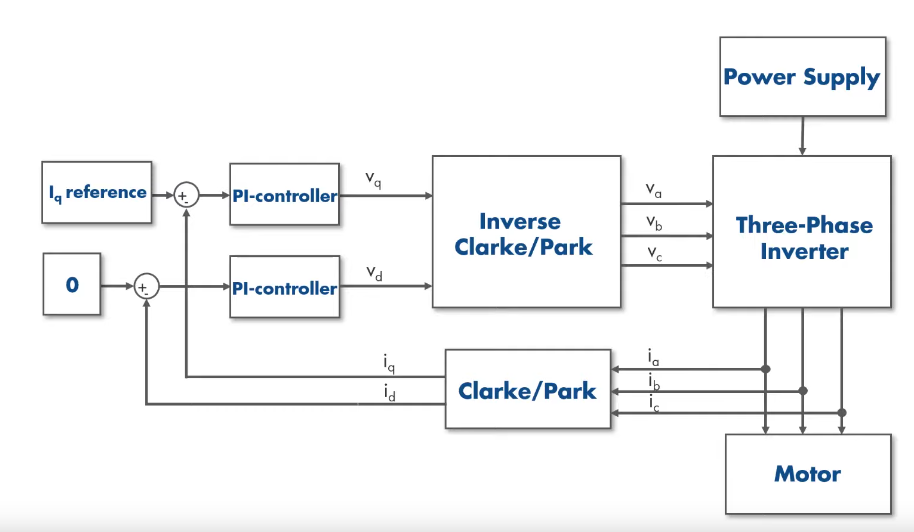
Field oriented control is a much more involved BLDC motor control topology enabling a high continuous torque output regardless of RPM. Please see this video for more information. At a high level, the onboard uC uses an absolute position encoder (in our case, a CUI devices capacitive encoder) to estimate a rotor vector, representative of the direction & strength of the rotating magnetic field resulting from the motor’s rotating magnets. The uC uses in phase current sensing to determine (and the inverter to control) a stator vector representing the magnetic field from the motors stationary coils. To generate the highest torque, the stator vector must lead the rotor vector by 90 degrees. A stator vector of higher magnitude will result in a higher voltage difference across the coils, a higher current through the coils, and a higher motor acceleration. Mathematically, the stator vector is broken into a quadrature and direct vector that are controlled by two separate PI loops. Mathematical transforms called the Park and Clarke transforms are required to map from phase currents to direct and quadrature vectors, and the inverse of those same transforms are used to map from those vectors back to desired phase voltages to drive the motor.
Hardware Implementation
Preliminary Motor Controller Schematic
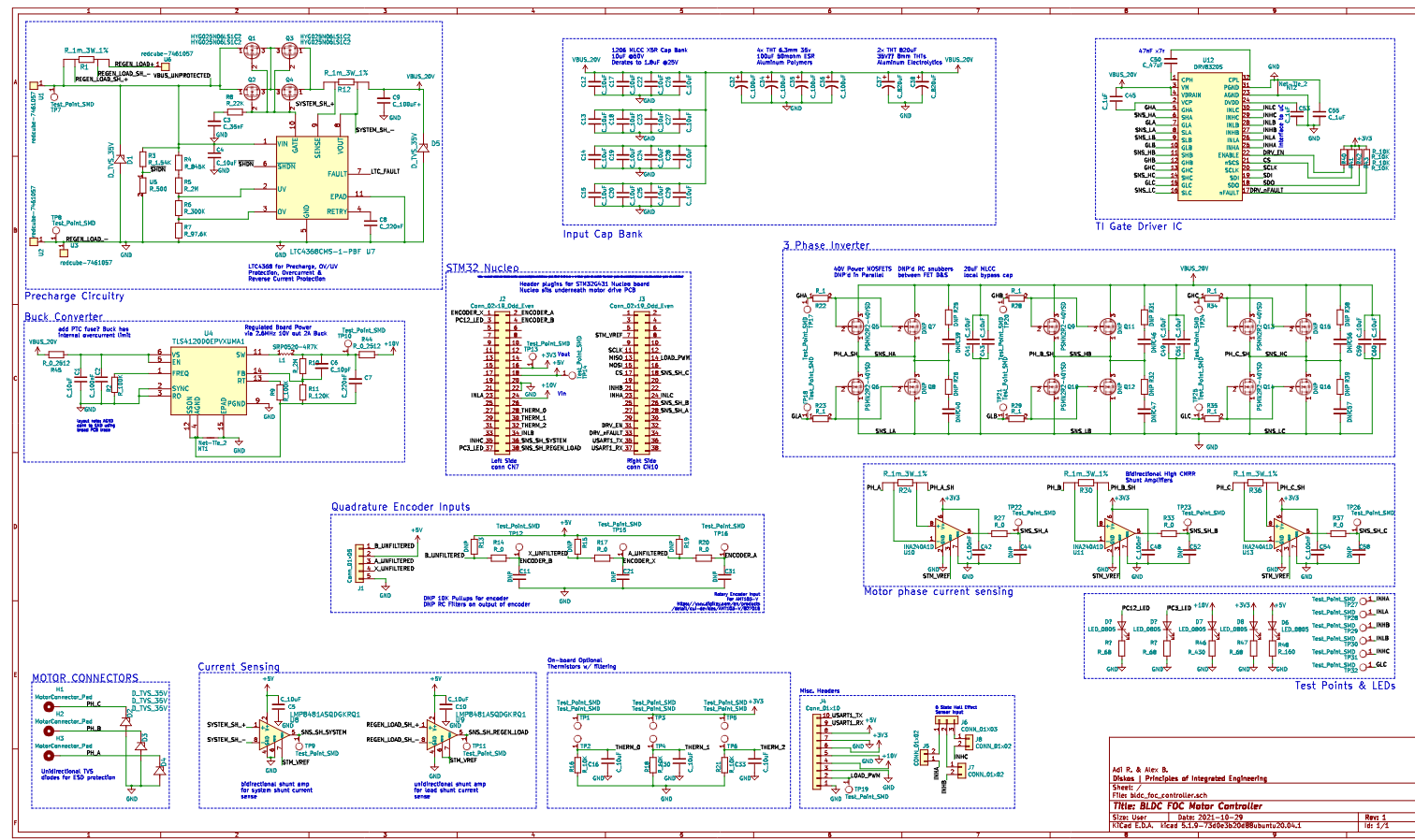
Schematic
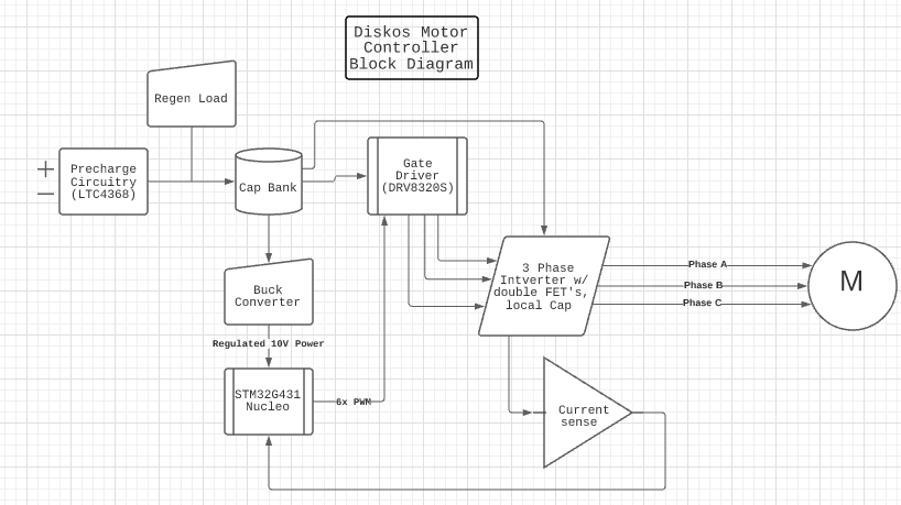
Brief Key Features of the system: FOC based motor drive, 20V VBUS w/ 40V gate driver FET’s, hardware to support active regenerative braking, 24KHz, switching frequency in phase current sensing, support for thermistors, CUI capacitive encoder or Hall effect encoder.
LTC4368 Protection Circuitry
The objective of this circuit is to handle precharge of the capacitor bank on the board and protect the rest of the motor controller circuitry from OV, UV, overcurrent events, & be able to rapidly cut the rest of the board off from power. The high side switch controlled by the LTC chip consists of a pair of source to source NMOS’s, paralleled (for lower conduction losses) (so a total of 4 FETs), (HYG025N06LS1C2) with a 2.1mOhm Rds(on) and a 60V Vds. Our selected values for this system were OV = 32V, UV = 10V, Iinrush = 10A. We also placed SMCJ22A-13-F TVS diodes with a breakdown voltage of 35V on either side of the LTC chip, to prevent both the input and output of the LTC chip from transient overvoltage events, and also act as freewheeling diodes under specific circumstances.
Gate Driver:
Our gate driver, the DRV8320RS, handles gate drive for our 3 phase AC inverter circuitry. This is a highly configurable BLDC motor controller gate driver IC from TI that we communicate with over SPI (from our STM32 uC). This chip can handle up to 60V VBUS, and drives all 6 FET’s in our inverter using 2 PWM signals per half bridge (a total of 6 PWM signals from our uC). The chip also reads high and low side voltages for each half bridge. The chip allows the uC to set gate currents, configure deadtime, and poll motor drive errors. We plan on driving the gate driver and FET’s at a switching frequency of 24KHz. This is a frequency empirically tested & recommended from our liberator & Messiah, Solomon.
3 Phase AC Inverter
At its core, a 3 phase AC inverter consists of 3 half bridges, where the high and low side FETs are switched on and off at their own duty cycles to create three sinusoidal voltage (and current) waveforms, to be fed into each phase of the BLDC motor. Each high side and low side consist of 2 paralleled NMOS FETs, (PSMN2R2-40YSD). These FET’s are 40V Vds with an exceptionally low Rds(on) of 2.1mOhms and gate charge of . The FET’s come in an LFPAK56 package, a common choice for motor controller half bridge FET’s featuring low thermal resistance. Please see our table below for a full comparison. Parameters compared include power dissipated during conduction, switching, and over FET’s body diode (this happens during deadtime when neither high or low side FET is on), as well as junction thermal resistance at an ambient 25C. We can back out the rise and fall times, which is useful for calculating switching losses & whether or not we can hit our desired switching frequency.
| FET Parameters | Output Values | Necessary Calculations | ||||||||||||||
|---|---|---|---|---|---|---|---|---|---|---|---|---|---|---|---|---|
| FET P/N | Global Stock | Package Size (mm) | Price/ea ($) | RDSon (10V) (mohm) | Qg(tot) (10V) (nC) | Rth(j-mb) (K/W) | Rth(j-a) (K/W) | Diode Vf (V) | Pd (cond) (W) | Pd (SW) (W) | Pd (Vfw) (W) | Pd (total) (W) | Tj (mb=25C) (C) | Tj (amb=25C) (C) | Trise (ns) | Tfall (ns) |
| PSMN2R2-40YSDX | 48 | 6.2x5.0 | 1.78 | 1.9 | 45 | 0.8 | 42 | 0.8 | 1.71 | 0.5832 | 0.0576 | 2.3508 | 26.88064 | 123.7336 | 45 | 22.5 |
| PSMN4R5-40BS,118 | 1200 | 15.8x10 | 1.75 | 3.79 | 8.8 | 0.65 | 33 | 0.75 | 3.411 | 0.114048 | 0.054 | 3.579048 | 27.3263812 | 143.108584 | 8.8 | 4.4 |
| SQJ142ELP-T1_GE3 | 4000 | 6x5 | 1.1 | 2.8 | 39 | 0.79 | 37 | 1.1 | 2.52 | 0.50544 | 0.0792 | 3.10464 | 27.4526656 | 139.87168 | 39 | 19.5 |
| BUK9609-40B,118 | 7000 | 15.8x10 | 1.71 | 6.2 | 134 | 0.95 | 33 | 0.85 | 5.58 | 1.73664 | 0.0612 | 7.37784 | 32.008948 | 268.46872 | 134 | 67 |
Since FET’s are non-ideal and non-identical, the miller capacitance curves between FETs on an individual basis will be different. To prevent ringing between paralleled FET gate capacitances, and ensure that paralleled non-identical FET’s get charged and discharged at the same time, we place a gate resistor in series with each FET gate & the gate drive line.
High frequency ringing can be present on FET turn-on & turn-off, so DNP’d RC snubbers between each FET drain and source are present as a precautionary move.
Each half bridge gets a little bit of its own MLCC low ESR & ESL local capacitance to pull on. See the input capacitance section for more on caps and why we chose MLCC caps here. The same principles behind why we have a cap bank on our PCB apply to why we have local capacitance in close proximity to each half bridge.
Cap Bank:
Our motor controller draws power from a benchtop PSU. The cables between that PSU and the motor controller hardware have a parasitic inductance that prevents current from flowing rapidly when transient loads are present (AKA, when the motor controller requests lots of current very quickly). Local capacitance on our PCB is helpful for this. Our input capacitance bank consists of 16x 10uF MLCC caps, 4x 100uF Aluminum Polymers, 2x 820uF aluminum electrolytic capacitors. The MLCC provides low ESR (equivalent series resistance) and low ESL (equivalent series inductance) but is fragile, takes up board space for the amount of capacitance it has, is expensive, and derates at lower & higher voltages significantly. The Aluminum Polymer capacitors offer low ESR and are a middle ground between MLCC & AlElec. The Aluminum Electrolytic capacitors act as bulk capacitance for low cost, but have a high ESR and ESL.
In phase current sensing:
Current sensing is required in order to complete the electrical feedback loop and provide information back to the uC. This is achieved with shunt current sensing chips designed specifically for motor phase sensing applications; namely they are bidirectional and feature a high CMRR, limiting their noise during 24KHz switching of the common mode voltage on either side of the sensed shunt resistor. We selected a gain of 20V/V to nicely complement and we’ve selected 4-wire 1mOhm 3W shunt resistors. The output has DNP RC filters, and as with every DNP’d component on this PCB, are precautionary but will hopefully go unused.
We plan on providing a voltage reference and running that ref trace as a differential pair with the current sense output signals to the uC’s ADC’s. The uC will use diff ADC’s for its conversions, in an attempt to prevent EMI from the inverter from inducing noise into the common mode of our shunt current measurements. The signal integrity of our shunt current measurements matters the utmost. Our reference chip must be able to provide a substantial amount of current (note the low required input impedance Rain for the SAR ADC’s on the uC at ~48KHz) and have a low tolerance, as we’ll likely be sampling our ADC’s at 14 bits … so it’ll be expensive. It has not been selected yet.
STM32G431RB NUCLEO:
Our Nucleo does all the heavy lifting calculations for FOC. This mainly includes the 24KHz timing requirements of the gate drive PWM signals, very precisely timed 48KHz ADC sampling for each of the 3 phases, heavy floating point calculations to map from phase currents to a stator vector to quadrature and direct vectors (and back to phase currents), and two PI loops to control the calculated quadrature and direct vectors. And don’t forget, since we’re running the motor at a velocity setpoint, we’ll need a 3rd PI loop to track velocity and adjust the desired quadrature vector.
The STM32G431RBT6 uC is one of newer STM uC’s and features built in motor control timers (making our lives easier when dealing with timing the ADC samples in between our PWM outputs to the gate drive), and also has an FPU to do more math, faster. It isn’t available online, #chipshortage #covid #whydidntIdosoftwareFML, so we ran with a Nucleo board featuring the same uC, and slapped headers on to our motor controller PCB.
Regenerative Braking Circuitry:
Features a simple current sensing scheme with the same 4-wire 1mOhm 3W shunt resistors in series with the load. Our intention was to design a variable load regen circuit and place the components on a separate PCB.
The circuit would look like a FET in series with a load resistor, where we could toggle the gate with a PWM signal to set the desired current into the load resistor.
Additional Considerations:
Our motor controller PCB additionally supports reading thermistors with some RC filters, features headers for a hall effect encoder, and has ESD protection diodes on the phases to prevent destructive spiking from external to the PCB. We also planned on interfacing with this motor controller over UART to the microcontroller.
Layout
We are partly through PCB layout at this time. Motor controller layout requires tremendous & special consideration with regards to: component thermals, routing of high frequency high current gate drive circuitry, routing of high current motor phase traces, placement and proximity of local capacitors, routing of sensitive signal lines near said high frequency traces, did I mention thermals, and more. #whydidntIdosoftwareFML
Proposed Firmware
Please reference the STM32 Nucleo section & the FOC explanation section. We plan on using PLECs Coder to generate parts of our firmware (especially the register level initializing code) for the uC, along with some of the floating point math & PI loops. Much PI loop tuning, auxiliary sensor readings, configuration for our specific hardware, will need to be written.
Terminology
Throughout our dive into motor controller design, we found there to be an influx of new information and terminology which front loaded our work. We found these notes to be helpful when reading / digesting motor controller design information.
Brushless DC (BLDC) Motor:
A Brushless DC motor (BLDC) is composed of all windings connected in a triangle or Y formation (the stator) and permanent magnets (the rotor) in close proximity. When the windings are powered in a proper sequence, these coils create electromagnetic fields that push against the magnets, rotating the motor’s shaft. There are two classifications of BLDC motors, inrunners and outrunners.
Outrunner BLDC:
An outrunner BLDC is a motor configuration that places the rotor on the outside of the motor’s construction and the stator on the inside. Overall this configuration has better torque specs than comparable inrunner configurations due to this construction.
Inrunner BLDC:
An inrunner BLDC is a motor configuration that places the stator on the outside of the motor’s construction and the rotor on the inside. Overall this configuration has better rotational speed than comparable outrunner configurations due to this construction.
ESC:
An Electronic Speed Controller is responsible for converting a digital PWM signal into a powered motor output. More advanced motor controllers incorporate more features, such as regen braking, system sensing, and overall better board design. We’re driving a three-phase BLDC motor and plan on putting energy into the system and pulling it out; efficiency is a priority. To accomplish this we’re using a motor controller that has a three-phase inverter to drive the motor, regen braking to pull energy out of the system, and uses a field-oriented control topology.
Three-Phase Inverter:
When driving a BLDC motor, each winding in the stator is energized to produce an electromagnetic field that pushes against the rotor, with each winding being powered with a 120° degree offset. To achieve this three half-bridges are tied in parallel to power each of the three phases of the motor.
Regen Braking:
While powering the motor from the inverter, the stator is energized and pushes against the rotor. When the motor is no longer being actively powered, the stator and rotor rotate past each other inducing a back electromagnetic force (BEMF) across each winding of the motor. This current goes into the inverter circuit and flows in a closed loop through the inverter’s components, with this pent up energy being dissipated as heat. In a regen braking system, the inverter can be activated in a sequence to actively brake the motor. In this sequence, current flows out of the motor and into the inverter’s VBUS rail. A simple load circuit (such as load resistors) can be utilized to dissipate this active braking current and prevent voltage spiking on the bus voltage rail.
Topologies:
Aside from the type of motor that is being powered, motor controllers can have many different architectural designs based on how they play on controlling and driving the motor. These designs are called topologies and they are usually baked into the overarching design of a motor controller as it can affect a wide range of specifications of the motor, such as what motors its compatible with (sensed vs nonsense motors) or even being able to create virtually infinite windings in the motor that all deliver peak torque to the rotor (See FOC). However, these Topologies with greater features usually come at the cost of greater system design complexity.
Gate Driver:
While the inverter passes power onto the motor, in order for each phase to be aligned correctly with the position of the rotor a Gate Driver is necessary. A gate driver takes a bus of digital PWM input signals (corresponding to the desired acceleration from the half-bridge), and outputs the gate signals for each low and high side FET along the inverter half-bridges. Additionally, the gate driver can have other features: such as protection from catastrophic failure modes, supplemental input from phase current sensing for more complex topologies, as well as communication between the microcontroller and the gate driver to indicate what faults have occurred.
Inductive Kick:
When suddenly turning off a system with large amounts of parasitic inductance, the system will curb its current consumption much quicker than the parasitic inductance can dissipate its energy. This causes an incredibly high voltage to build across non conducting components. While momentary, this kick can easily blow fets and other circuitry.