Software & Sensing Suite
In-depth documentation covering the implementation and design about software and the sensing suite it handles

Arduino Firmware
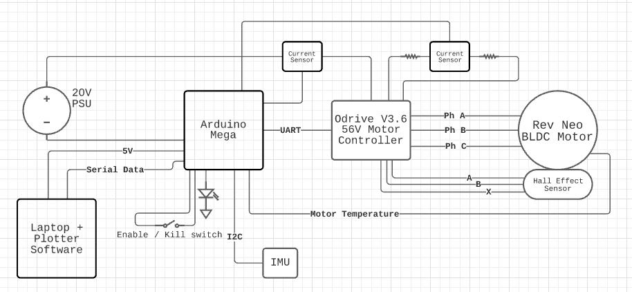
All control firmware runs in a super loop on an Arduino Mega. The objective of the control firmware is to safely operate the flywheel in an autonomous manner, and provide metrics about its operation to a user. The control firmware must be able to:
- Interface with the Odrive motor controller to set the velocity setpoint and velocity ramp rate of the flywheel motor.
- Power and poll the sensing suite to collect critical data about the flywheel’s operation
- Continuously perform safety checks and automatically shut the flywheel system down if needed
- Relay sensor data & critical information over a serial connection to a connected laptop
The Arduino code features three finite state machines (FSM’s). Each of these FSM’s is implemented in code with a switch statement in the Arduino’s superloop, which executes the appropriate function respective to the state. The state machines track:
- System state, to track whether the overall system should spin or not.
- RUN
- STOP
- Odrive state to track exact state of flywheel spin.
- FAULT
- IDLE_
- STARTUP
- REGEN_BRAKE
- REGEN_SPINUP
- SPINDOWN
- Startup state to track flywheel startup regime
- STOPPED
- SPINUP
- MID
- FAST
- COMPLETE
In order for the Arduino to Interface with the Odrive motor controller, we use the Serial1 peripheral available on the Arduino Mega at a baud rate of 115200. We use 2 serial ports on the Mega, with Serial being used for communications to the laptop, and Serial1 being used for communicating with the Odrive. Using the Odrive’s ASCII Serial interface, we communicate to UART_A on the Odrive to read and write data from the Odrive and commands to the ODrive, respectively. More on the data we read from the Odrive later. The main commands that we write to the Odrive are setting the velocity setpoint and setting the velocity ramp rate. We also have the ability to clear errors on the odrive.
Our Sensing Suite
A GY-521 IMU breakout board
This board breaks out a MPU6050 IC, which yields 3 axis gyro & accelerometer that collect data at 8KHz and 1KHz respectively. We poll the IMU at 1KHz over 400KHz I2C. Ideally, we’d be able to poll it faster, but since our Arduino runs a superloop and also needs to manage high speed serial communications with the Odrive & the laptop and perform safety critical checks & basic floating point calculations, we decided to ease the load on the Arduino and reduce the rate at which we poll the IMU down to 20Hz. This is not ideal for collecting high frequency IMU data. We run an IMU to determine system vibration; it is mounted on the bottom bearing block, and its data is particularly useful for dynamic balancing and high speed RPM testing.Internal Neo motor temperature sense line:
This line is a low side 10K NTC thermistor. We have wired a 10K pullup and poll the voltage at 3Hz using the Mega’s onboard 10 bit ADC’s. The motor is one of the primary loss mechanisms in the system - the higher phase current we run through the motor, the higher power dissipation, and the hotter the motor gets. The motor’s internal temperature should not exceed 80 degrees C, and operating it continuously at high speeds requires constant monitoring of the internal motor temperature. Ideally we would have motor housing temperature data, ambient temperature data, and bearing block temperature data.Input current & regen current sensing:
Both are tracked with separate ACHS-7124 Pololu breakout boards, that breakout ACHS-7124-000E 40A bidirectional ratiometric hall effect sensor IC’s. we poll both current sense lines at 3Hz using the Mega’s onboard 10 bit ADC’s. The max current spec on these sensors was likely too high, resulting in a lower precision current sensing setup. This data can help us indicate the input power to our electrical system, as well as the power being dissipated over the brake resistors.Additional Data that we poll from Odrive Motor Controller
VBUS - Bus voltage
Helpful in indicating input power to the system.Revolutions / Second (RPS)
We poll the Odrive’s encoder velocity estimate, stored in the axis1.encoder.vel_estimate variable, which is returned in a units of RPS. We multiply the returned value by 60 to track RPM data.Errors
- System error
- Axis error
- Motor error
- Sensorless Estimator Error
- Encoder error
- Sensorless Estimator
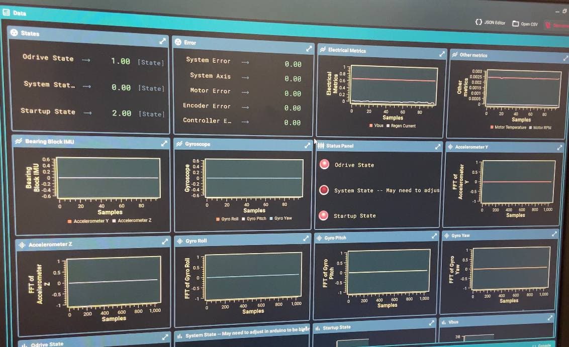
We send data over serial to the laptop at 50 Hz. Serial data is colon delimited to interface with the Serial Studio live plotting display software.
Our fault checking consists of checking for motor overtemperature at 80C, any present odrive errors, and the kill/enable switch that we have on our system to power down.
In the current system, our fault handling procedure consists of simply setting the Odrive velocity setpoint to 0 RPM with a conservative (slow) vel_ramp_rate of 0.5. In future systems an active magnetic eddy-current brake may be utilized.

Data Vizualization with Serial Studio
Built right ontop of our serial port, on the laptop we have reading data from the Arduino is our configuration of Serial-Studio. While not much complexity exists in creating this setup, its addition allows for a clear visualization of the data that is being sent over serial as well as allow a great ui for saving the data too. Since one of the overarching goals of this project was to create a testbench for development post PIE, having a Labview-esk front-end live visualization of our data we found was a nice touch