Manufacturing the Flywheel
Blurb about the assembly -- 1-2 sentance takeaway
The Flywheel Disk
Making the flywheel disk started with a piece of six inch diameter rod about five inches long that has been sitting outside the shop for years. We got permission to use the stock and first proceed to try to identify the material. Using the XRF gun in the Material Science lab, we got the elemental makeup shown in table 1. This, combined with a spark test, led us to believe that the stock is low carbon steel.Table 1
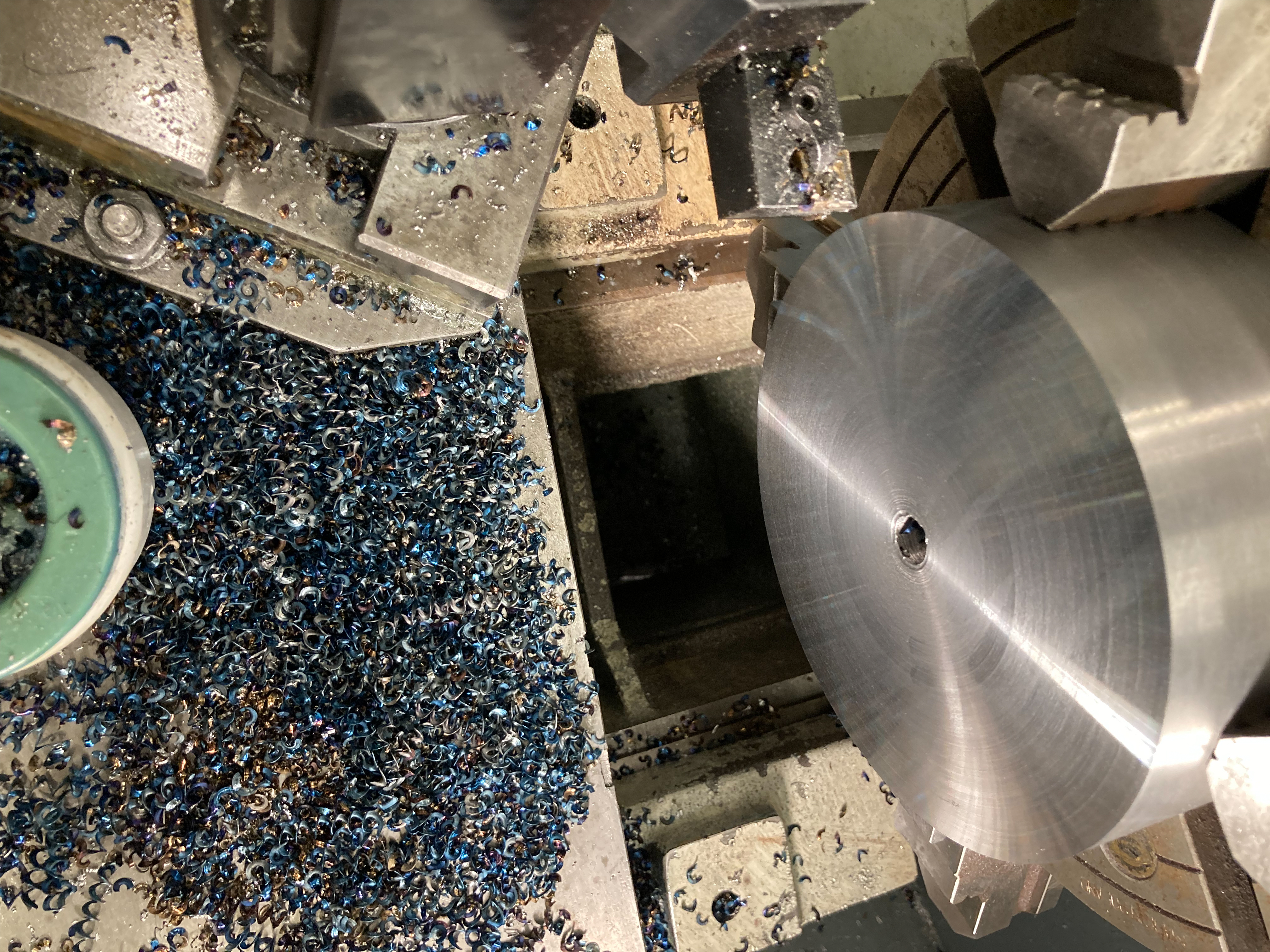
After identifying what we were working with, it was time to chuck up the stock in the lathe and take some heavy cuts. There were a few fifty thousandths DOC facing passes where it was an interrupted cut due to the saw cut face, but once the face was cleaned up, I took a few heavier passes to really make some chips. On the finishing facing passes, Nate recommended spinning it up to 600rpm and then manually feeding quite quickly at the beginning and then slowing down as the surface speed dropped closer to the center of the piece. Using the horizontal bandsaw I cut the part from the remaining stock then faced the backside and drilled and reamed a .750” hole. The original plan was to ream a morse 2 taper through the disk and then turn and grind the axle, but we decided that using a shrink-fit between the disk and axle was both easier and sufficient for our application. With the disk complete, it was time to make the axle.
The Axle
We used one inch diameter 41L40 bar stock from McMaster. This alloy steel had good mechanical properties for our application as well as easy machinability. In hindsight, 4140 without the added lead in 41L40 may have been a better choice due to the fact that though the added lead did allow chips to form more easily, the surface finish wasn’t as nice as a more ductile material.

Made some nice chips roughing the disk
The Axle Disk Assembly
We balanced the flywheel after it was assembled both statically and dynamically in order to ensure an even mass distribution and that the center of rotational inertia was inline with the axis of rotation. To do the static balancing we rotated the flywheel on its side resting in its enclosure and ensured that at every angle the disk didn’t have any torque making it turn such that the heavier part of the disk faced down. We also chucked the whole assembly in the lathe and measured the runout at different points and on different faces. There was less than one thousandths of runout in the assembly.
The Welded Frame
Welding the frame started by cutting stock to correct lengths. After cutting the stock, we arranged the pieces using clamps. Once we were satisfied with the alignment, we tacked the edges of the square tube together. We then ran beads down the edge faces and ends of the tubes to hold them together. This process was repeated for every joint on the frame. We did run into some problems with the thickness of the square tube, but that may have been a result of our amateur welding skill. After welding all the joints on the frame, we ground the welds and painted most faces. We also drilled holes for mounting hardware.

Squared up the rough stock for the bearing blocks

Drilled through holes before boring.
The Bearing Blocks
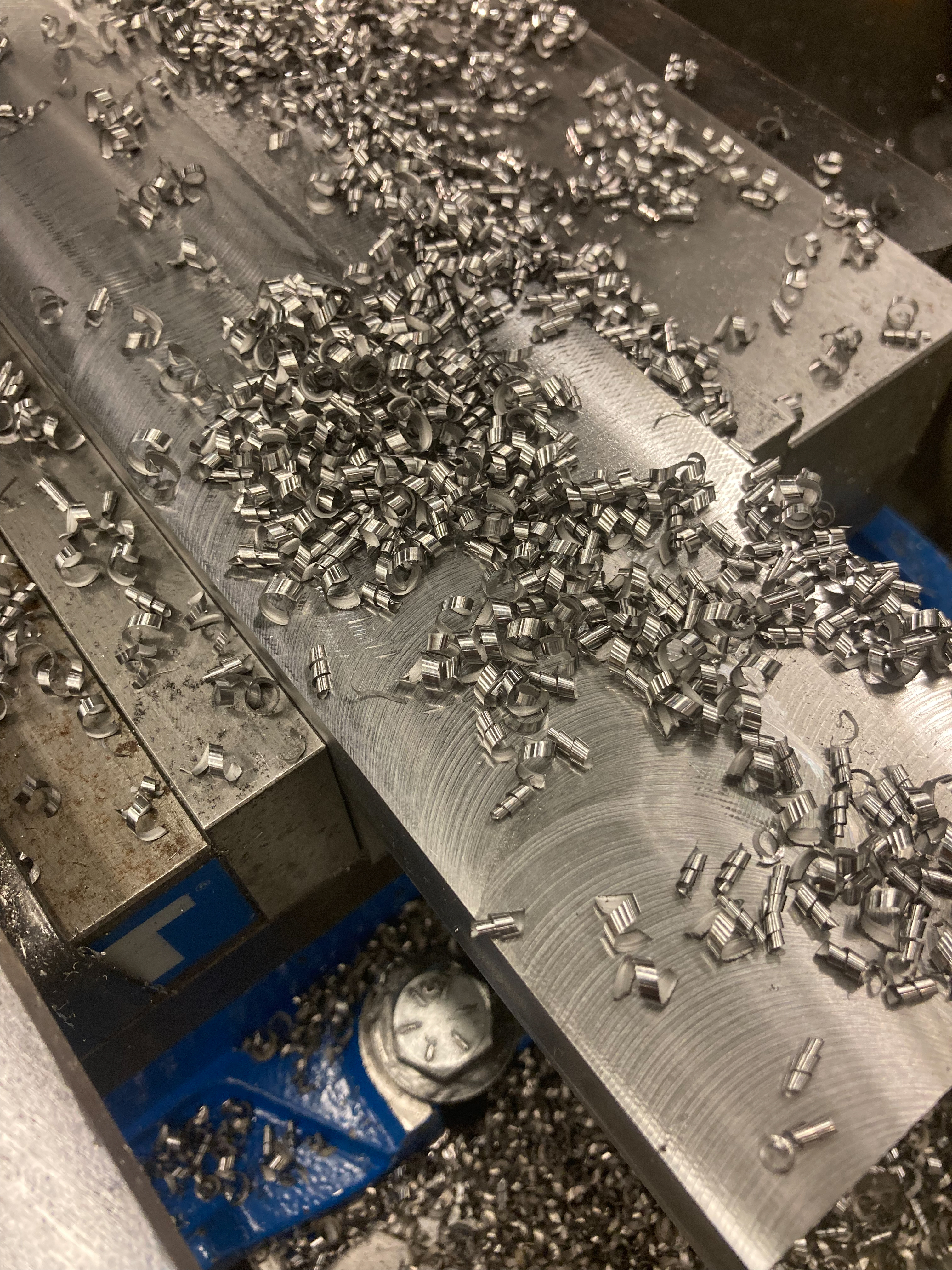
The bearing blocks started as a 1x4x15 inch block of hot rolled steel we got as a drop from the local metal supplier. We then roughly squared the stock and faced it to remove the mill scale and cut the blocks to length with the horizontal bandsaw. After the blocks were square and to length all that was left was drilling and counterboring the mounting holes, and boring the bearing recess to size. In hindsight, it would have been much more efficient to set up the bearing blocks in the four jaw chuck in the lathe and bore the holes that way. The boring head in the mill could only take cuts up to about twenty thousandths, and the process generally just took a long time. I was aiming for no clearance between the bearing outer face and the bearing block bore and then took a spring pass which resulted in a very tight but sliding fit.

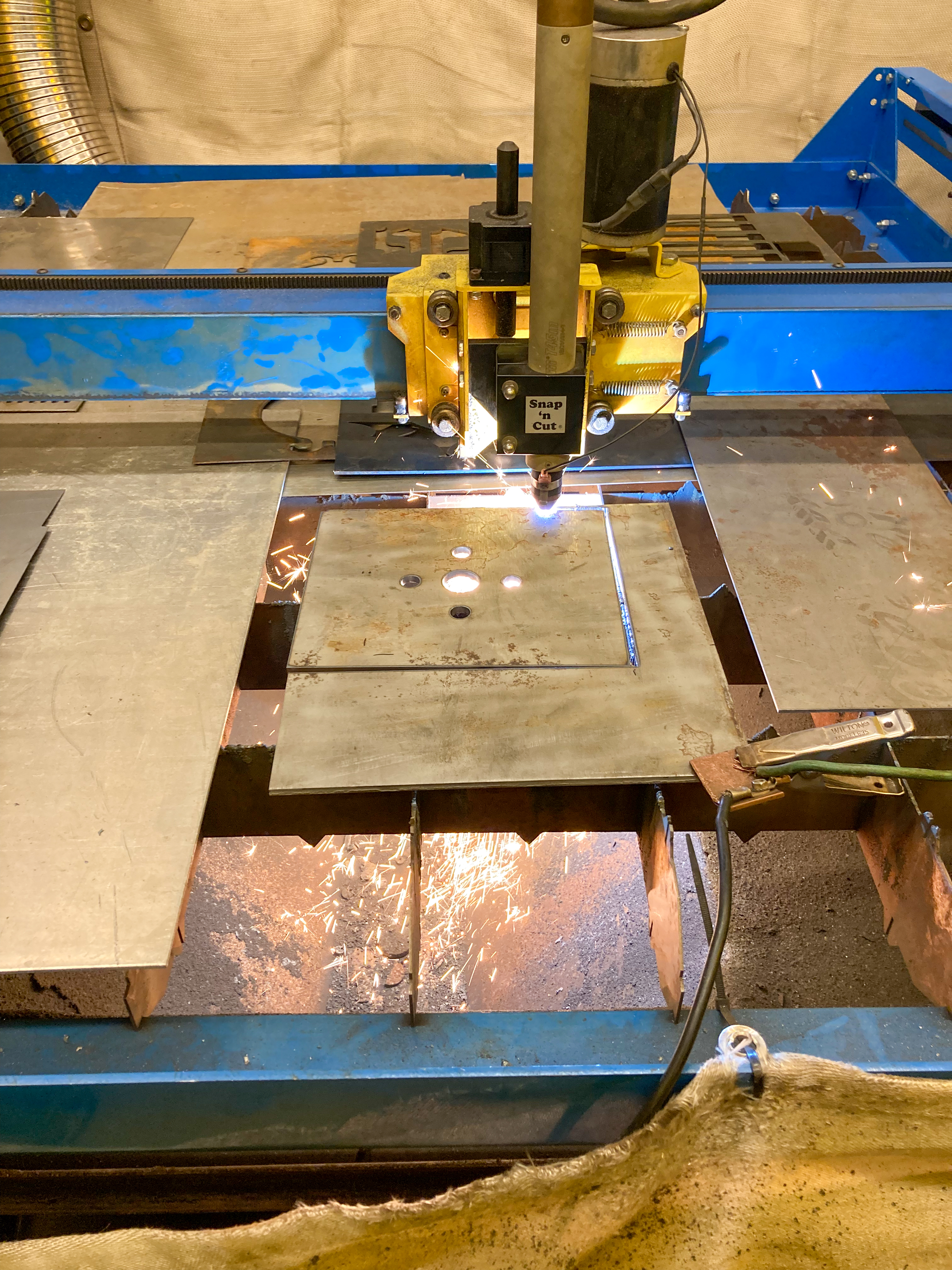
Cutting out the top plate
Miscellaneous
We cut the top plate for the enclosure with the plasma CNC out of quarter inch mild steel sheet. After taking off the slag, we set it up to drill four through holes to mount it to the welded steel frame.