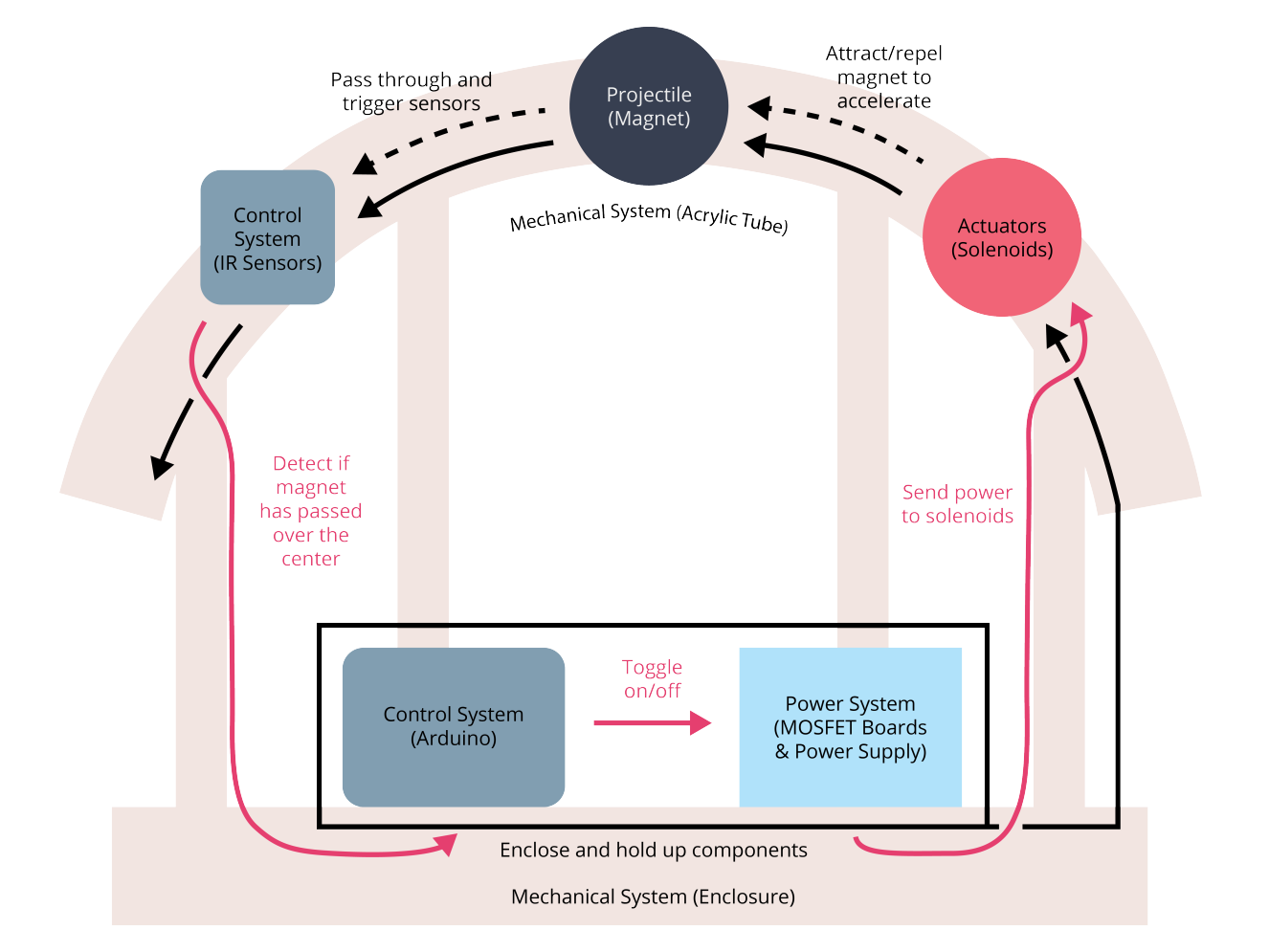
Final Integration

Mechanical System

There are three significant mechanical aspects to this project: the attachments on the tube to hold electromagnets and sensors, the acrylic tube, and the wooden box that houses the electronics and supports the tube. 
Tube Bending

Our final design took the form of a rainbow shape made of the same acrylic that we used in previous sprints. We found that this design would work best as it would return the magnet to a specific location on each side of the arc to allow for consistent and repetitive operation. To bend the tube we first tried to use a heat gun but found that this was far too unwieldy, so we resorted to using boiling water to heat larger portions of the tube and bend it around the jig. 

Wooden Housing

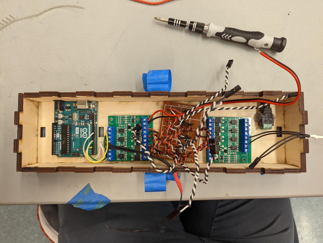
The wooden housing consisted of a box to hold the electronics and spokes to hold the acrylic tube. The box to hold the electronics has finger joints to ensure that it's as square as possible and as sturdy as possible. It also has cutouts in the back for the power cables for the Arduino.The spokes have living hinges cut into the top to allow them to bend to conform to the shape of the tube while still being sturdy enough to support the tube’s weight.

IR Sensor Mounts

“Arms” of the structure that hug the tube were made wider to provide more rigidity and strength, and a peg on top of a flat surface was used to constrain the circuit-board IR sensor through the screw hole.

Spool Design

 Spool centers were printed in phase mode, with a single layer of clear filament (just enough to keep wire on the outside)

Electrical System

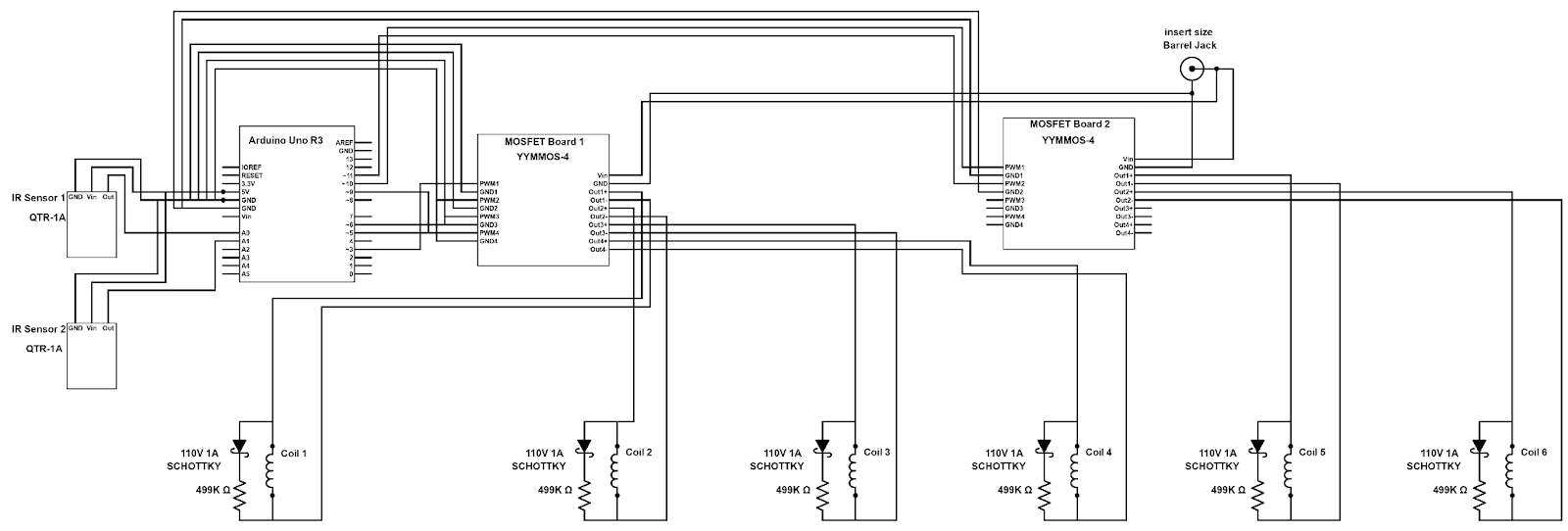
        SMAKS is controlled by an Arduino UNO, which toggles 6 MOSFETs across 2 YYMMOS-4 4-channel MOSFET boards. The MOSFET boards are connected to a benchtop power supply which supplies them with 24V DC power, and each MOSFET on the board triggers power being sent to a homemade solenoid. The solenoids on each end of the arced tube are wired to repel the magnet used as the projectile, while the four center solenoids attract. The solenoids and MOSFETs are wired together through perfboard that sends power from a MOSFET to solenoid in parallel with a 449KΩ resistor and a 100V 1A diode, which are used to prevent backflow from any charge generated in the solenoid by the magnet passing through. 2 QTR-1A IR reflectance sensors, one placed on each side of the acrylic tube, are wired directly to the Arduino and provide an analog input used to determine whether the magnet is above the sensor.   
        We determined the solenoid specifications through trial and error, changing coil length, turn count, and current, in line with the equation magnetic field = relative permeability * turn density * current, where the relative permeability of air (no core) is 1, turn density is proportional to turn count and inversely proportional to coil length, and current is controlled by wire gauge and input voltage. The final solenoids have 2000 turns of 32AWG magnet wire and are 0.8” long.
Firmware System

Our firmware system runs on the Arduino Uno and controls the solenoids. The control of the solenoids is a combination of sensors and timing to make the magnet consistently move over the arc and down the other side. A simple sketch runs on the Arduino with manual timing for the duration of each solenoid receiving power and the delay between solenoids triggering. We use while loops to continuously monitor the IR sensors after attempting to send the magnet through the tube, rerunning the same firing code until the sensor on the opposite side of the tube detects the magnet passing through.

View COde

Budget

We already had access to many of the items we used for this project, but the complete table of money spent can be found through the link below.

bill of materials