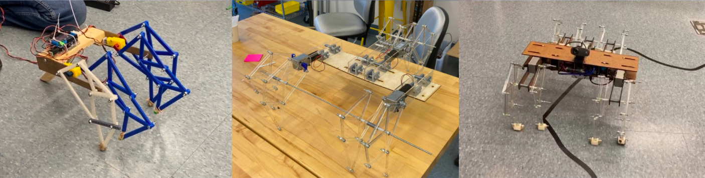
The leg design is based on Jansen's linkage, a linkage design made by
Theo Jansen for his Strandbeest sculptures. The legs needed to transfer
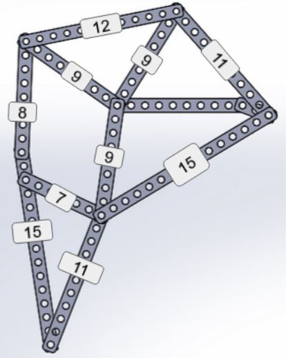
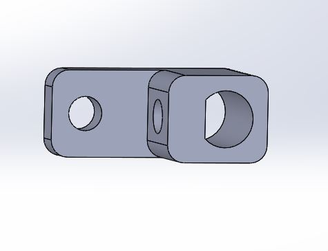
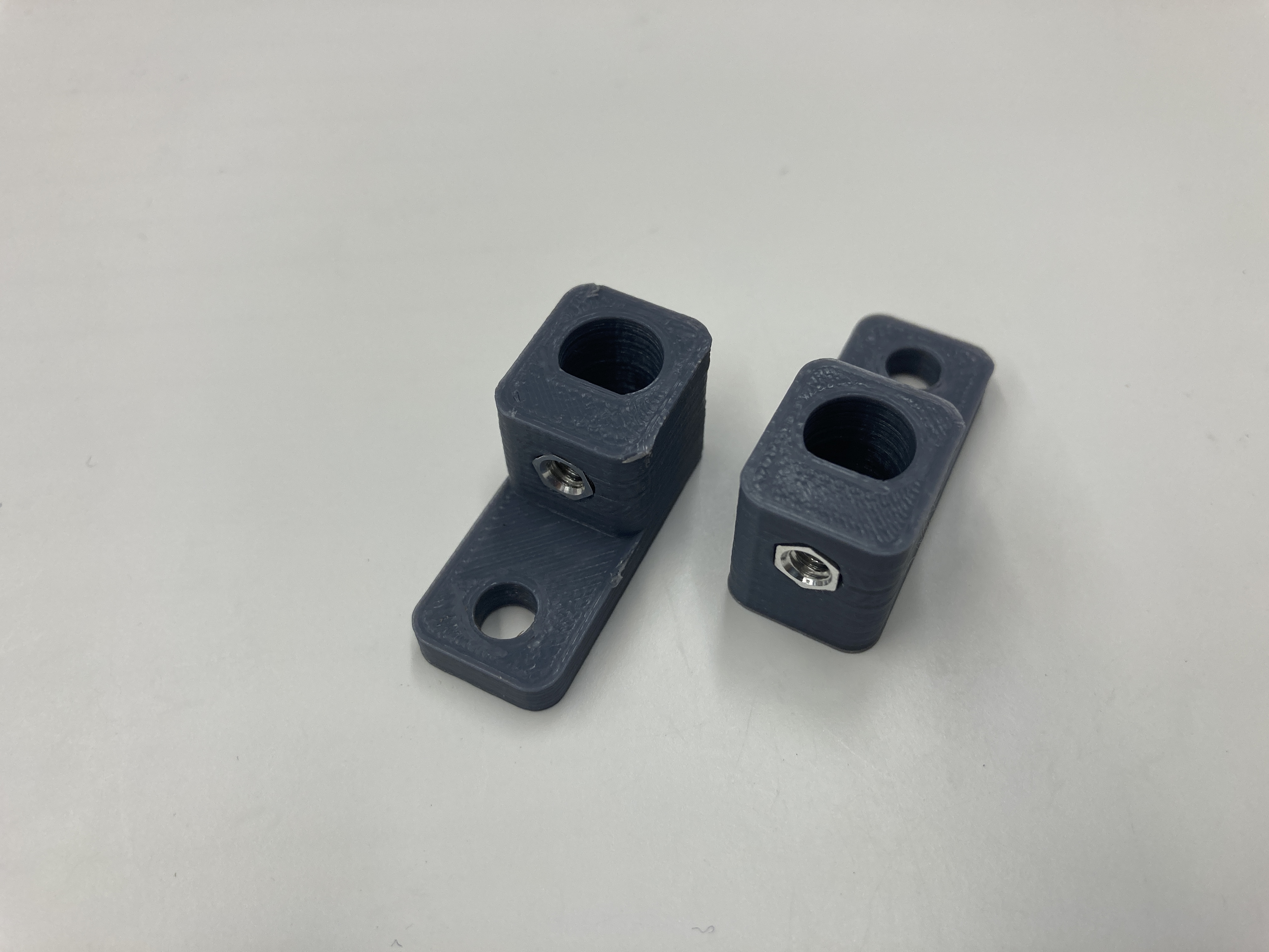
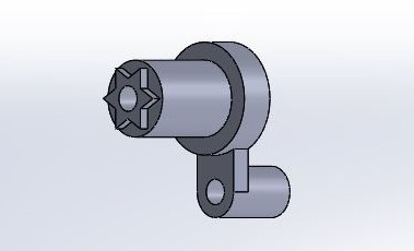
the rotation of the motor shaft into a stepping motion. The initial design
(shown right) was made to replicate the motion of the Jansen linkage.
Assuming we would need to make small adjustments, the first iteration of the
linkages were designed with future modification in mind; each linkage contains
bolt holes at 1 cm intervals to make small changes very easy. This ended up causing
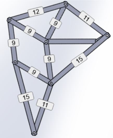
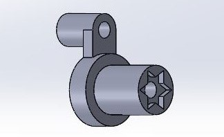
strength problems within the part so after the final lengths were determined the
design shifted to solid parts (shown left) in the second iteration. The other change
between the two designs are the modified linkage lengths. While the initial design
was optimized for the step pattern, the second iteration was designed for simplicity
while keeping a step pattern that would work on the robot. This simplification led
to using five 9 unit linkages making construction much easier.
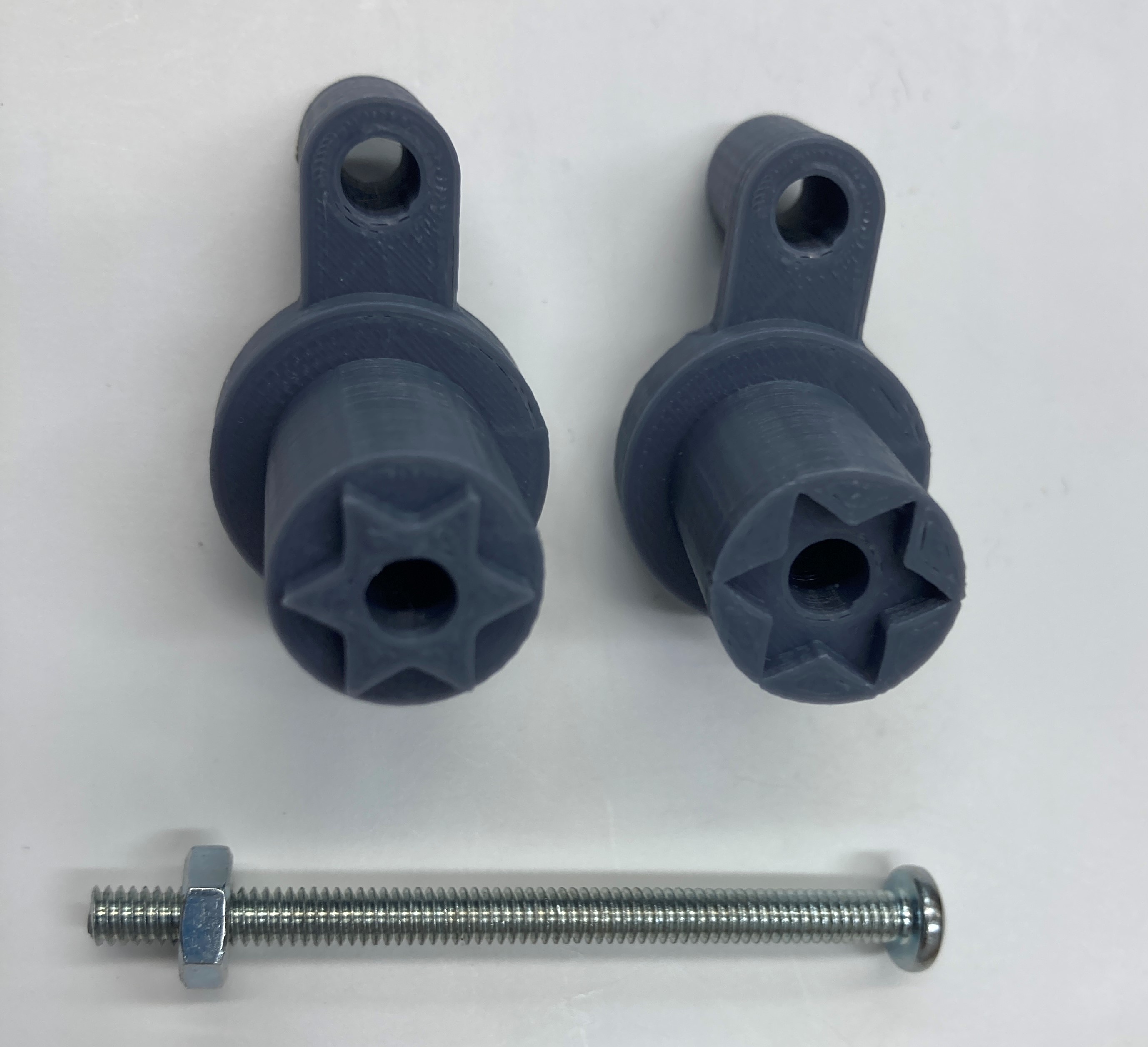
The first iteration of the legs used 3d printed linkages made of PLA printer filament.
This material was chosen because it’s a readily available prototyping material that our
team had experience using. The material proved to have too much friction for the motors
we were using, causing the legs to bind. In addition the print time for each leg was
roughly 5 hours, and printing 8 legs for the final design would have been a challenge.
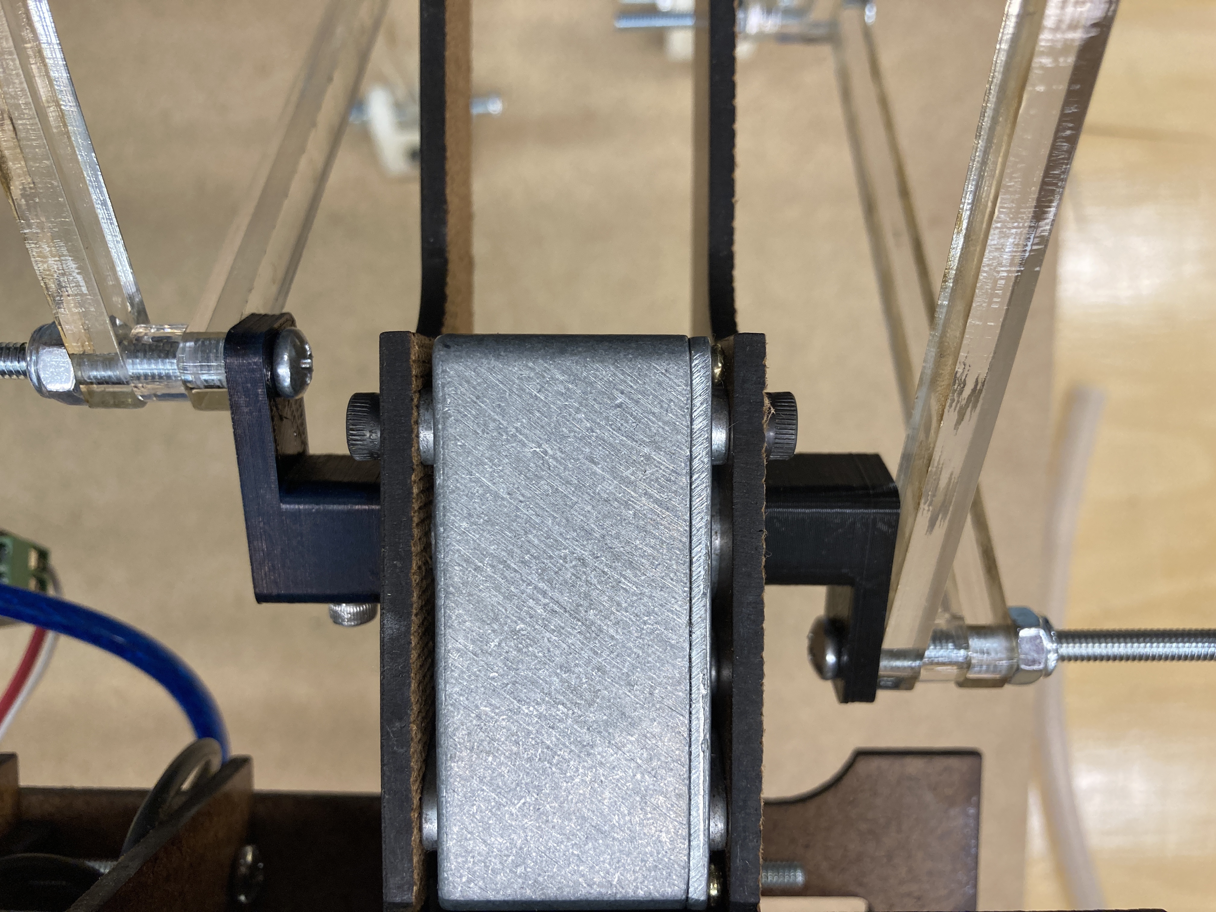
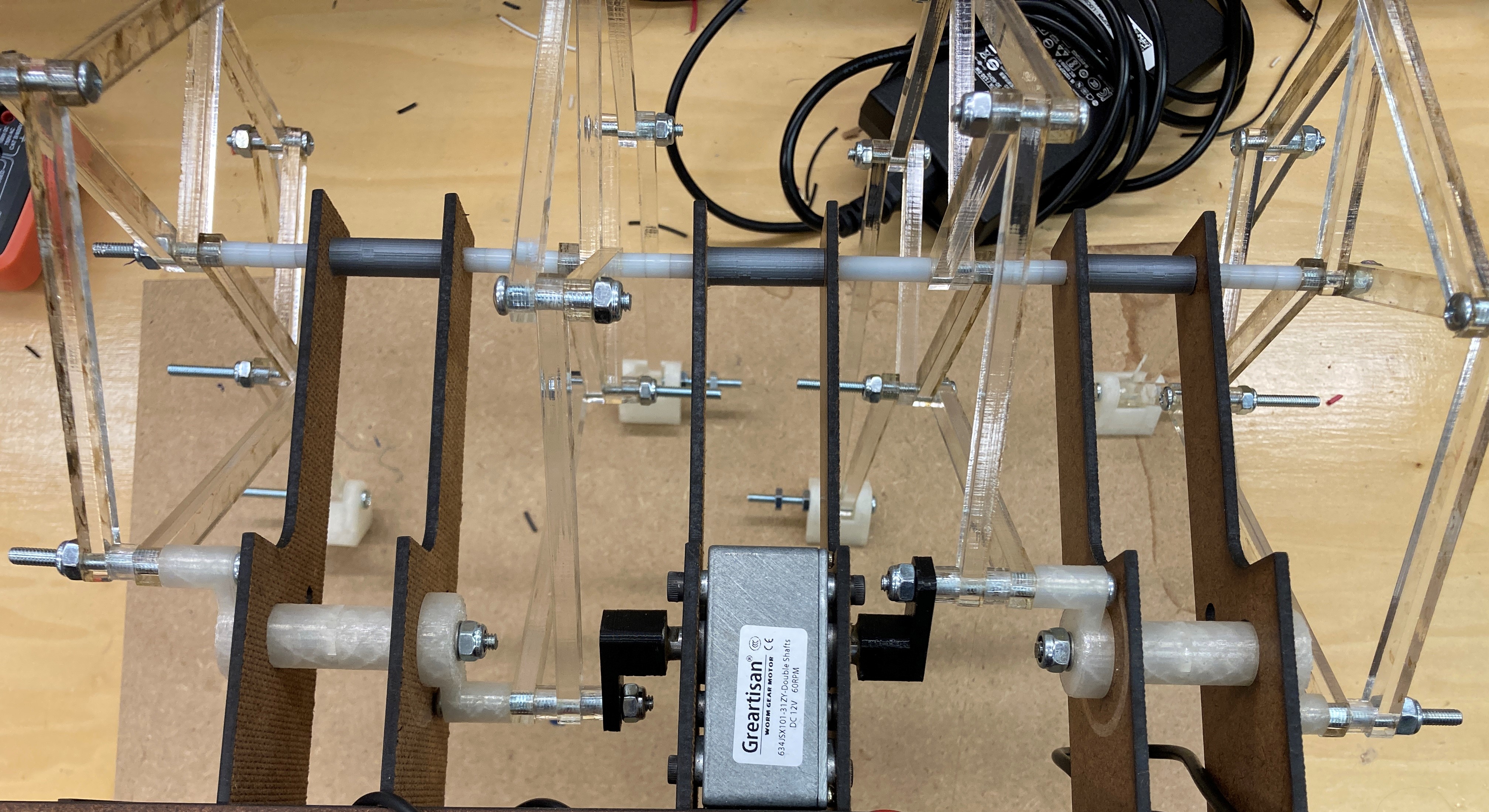
We decided to move to ⅛th inch laser cut acrylic for the second iteration. This allowed
us to cut all 8 legs on one sheet, reducing the manufacturing time significantly. The
acrylic also proved to have lower friction than the PLA, and when combined with the
higher torque motors we purchased (this is explained under motor selection) this solved
the friction problem. However, the new motors increased the weight of the robot and the
acrylic was not strong enough to counter the mass increase. The legs bent, and would not
function properly when holding the full robot. To solve this we increase the ⅛th inch
acrylic to ¼th inch acrylic. While there's still some bend in the legs, they are functional
and are unlikely to break.
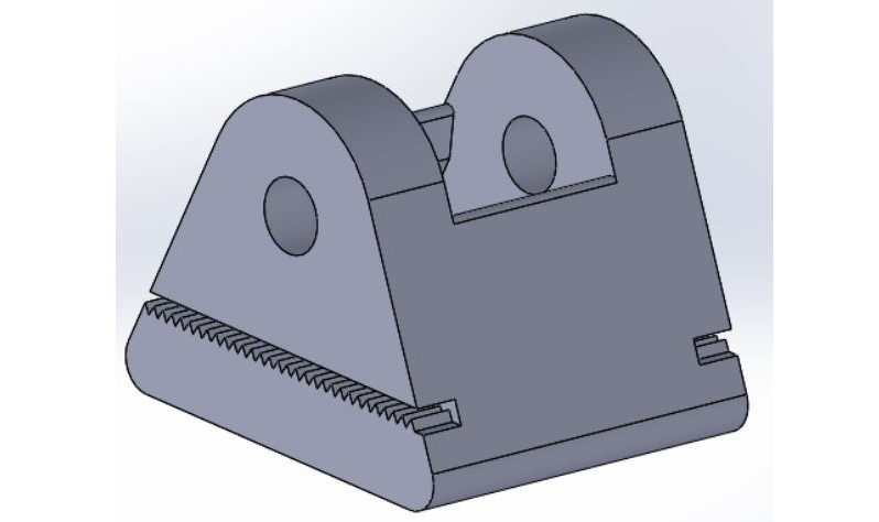
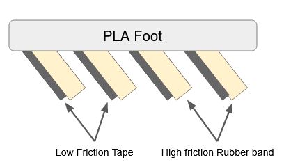
To solve the traction problem we added rubber bands to the pads of the feet. But the bending of
the legs meant that the feet would drag while trying to move forward. The solution was to make
feet that only had friction in one direction, pulling the robot forward then sliding back into
position. This was accomplished by putting the rubber bands on an angle, and adding a layer of
tape to the top. This means when the foot is moving forward the foot slides along the tape, and
when it is moving back the angled rubber catches the ground pulling the robot forward.