Our Process
We completed this project in three two-week long sprints. Here’s what we did in each one!
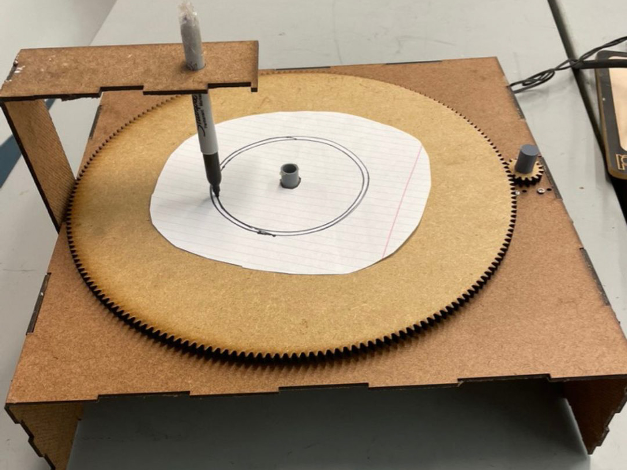
Sprint 1
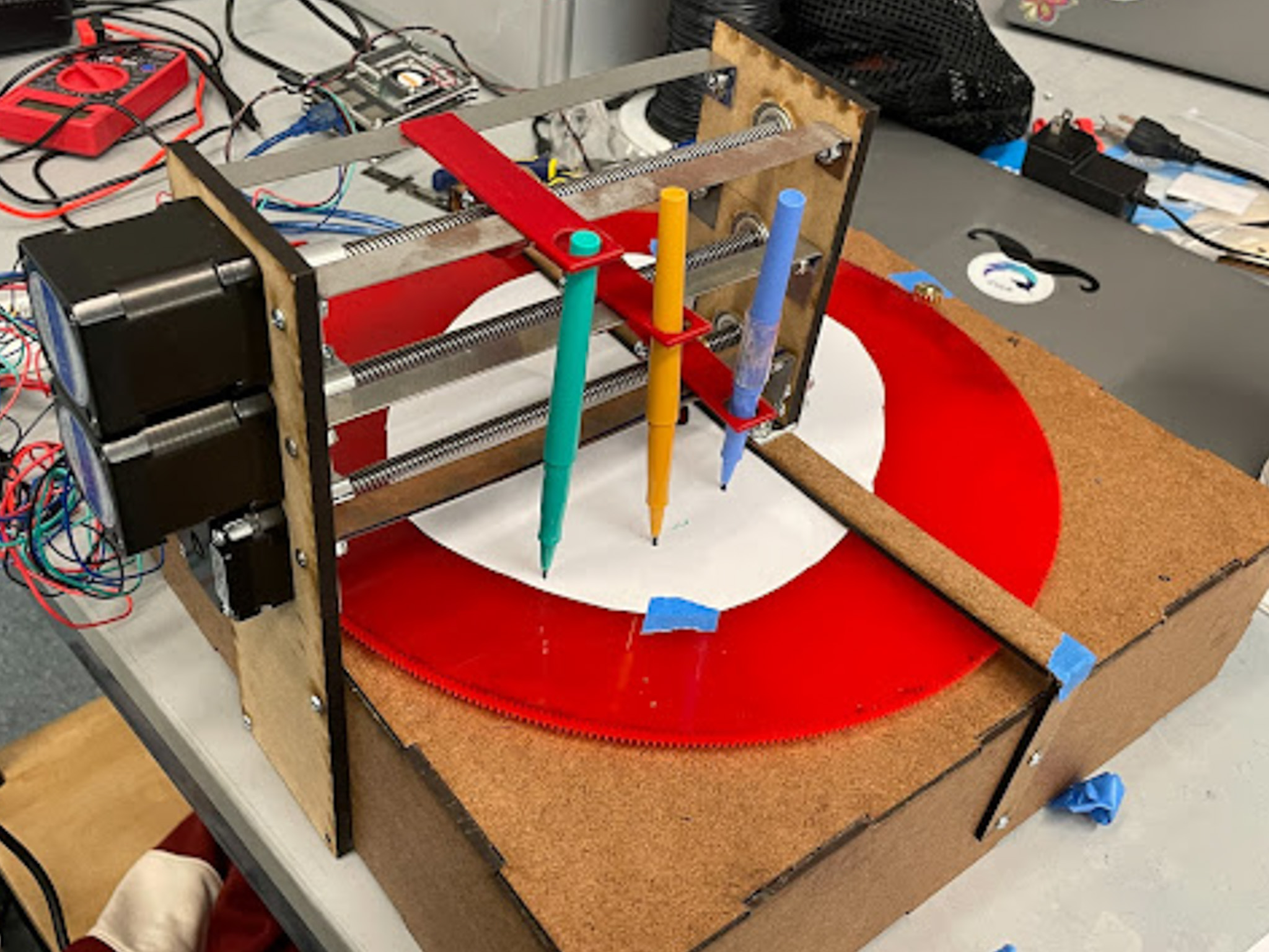
Sprint 2
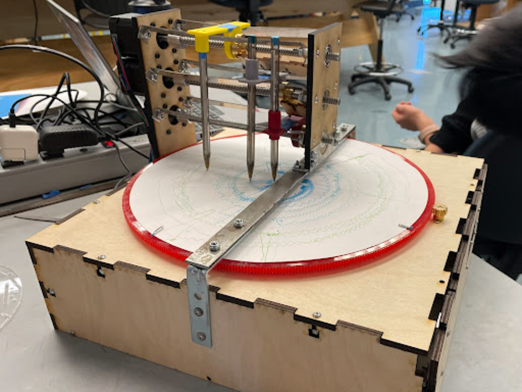
Sprint 3
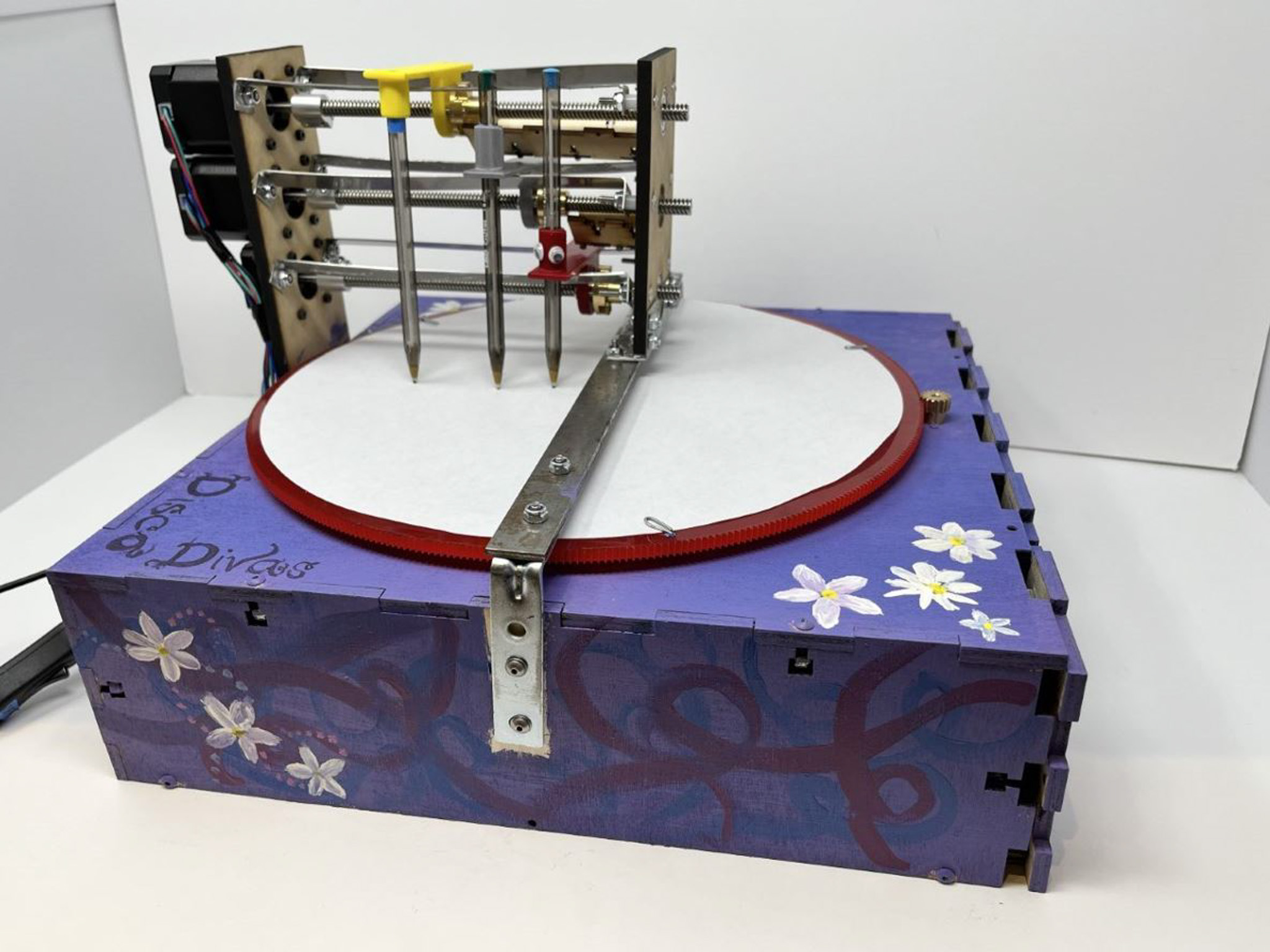
Final Push
We completed this project in three two-week long sprints. Here’s what we did in each one!