Software
Firmware
In our original vision for the project, we expected to be writing our own g-code generator and interpreter. As mentioned in our electrical systems summary, we decided to use a Protoneer CNC Shield, as it was an easy way for our Arduino to interface with the number of steppers we needed, along with limit switches and other accessories. When researching the CNC Shield, we discovered its compatibility with the GRBL firmware. GRBL presented the perfect opportunity for us to focus our time on configuring, tuning, and perfecting our system while based on an existing open-source firmware, as opposed to writing a g-code interpreter from scratch. Although it meant we wrote less code for this project, not reinventing the wheel allowed us to focus on rock-solid integration of our CNC router.
We did have to change some of the pre-configuration options of our GRBL source code to allow our DC motor driver access to the hardware PWM capabilities of pin 11 on the Arduino.
Software
 Once we
decided to use GRBL, we searched for a piece of open-source software that would allow us to
generate and send basic g-code commands to our Arduino. We settled on Universal G-code Sender as our sender of
choice. We used UGS to jog the gantry, testing our steppers and gantry. We were also able to use UGS
to edit GRBL's configuration variables, tuning axis lengths, max speed and accelerations, and
initializing our limit switches.
Once we
decided to use GRBL, we searched for a piece of open-source software that would allow us to
generate and send basic g-code commands to our Arduino. We settled on Universal G-code Sender as our sender of
choice. We used UGS to jog the gantry, testing our steppers and gantry. We were also able to use UGS
to edit GRBL's configuration variables, tuning axis lengths, max speed and accelerations, and
initializing our limit switches.
Once we got experience working with UGS, we were able to calibrate our limit switches at the positive
end of each axis, adding soft limits at the negative extremes. We also added a homing routing to all
3 limit switches, activated by sending the $H command. We also developed a standard
setup
procedure to zero all three axes and get the machine ready to cut.
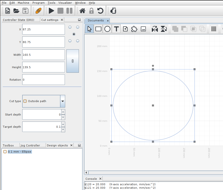
Once we progressed past configuration and jogging, we wanted to be able to design and generate g-code for simple patterns and shapes. This was easy, since UGS has this functionality built-in. However, since UGS can also send g-code files generated by other software tools, we are hoping to experiment with the 3D CAM capabilities of Fusion 360 and/or HSMWorks to generate much more complex 3D toolpaths.
Cut Setup
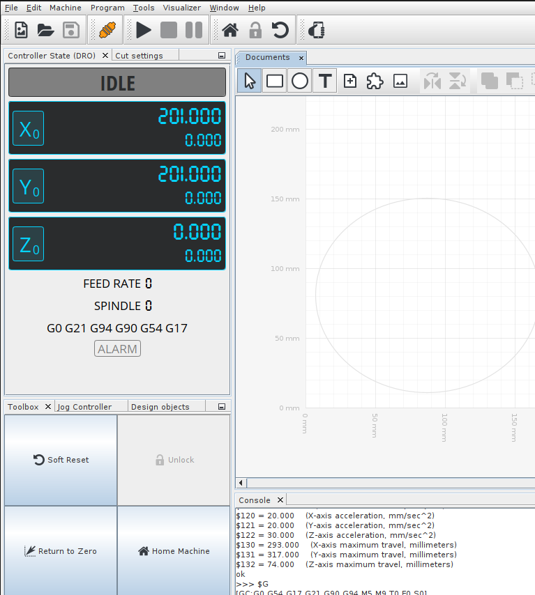 The process of
setting up a cut is rather simple, and is demonstrated in the below video. Once the
piece has been screwed to the spoilboard, the
The process of
setting up a cut is rather simple, and is demonstrated in the below video. Once the
piece has been screwed to the spoilboard, the $H command is sent, and the router goes
to all 3 positive axes to home itself. Then, the machine is manually jogged to the desired cut start
point and all 3 axes are zeroed. Once the axes are zeroed correctly, the cut file can be sent. The
zero positions persist after the end of a cut, but the home and zero should be reset to
mitigate possible drift.
GitHub
Although we did not end up writing any code in the final version of the machine, our GitHub repository includes our Sprint 1 code, wiring diagram, demo cut files, and GRBL files necessary to recompile and flash our configuration of GRBL to the CNC router.