Sprint Three - Integrating X-Y Gantry with Spindle
Overview
This sprint focused on combining the systems we developed in Sprints 1 and 2, focused on getting us a fully working CNC controlled gantry. Our gantry also went through a major redesign during this sprint, so integration ended up being a major challenge that we were excited to tackle.
Mechanical
 After realizing the tolerances and functionality in the gantry for Sprint 2 were less than
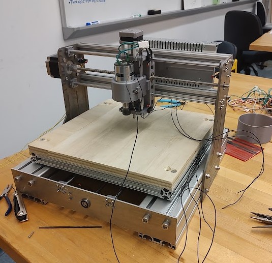
satisfactory, the mechanical team decided to go through a complete redesign. The bed and material
would now move along the X axis whilst the spindle would still move along the Z and Y axis. The
design was also simplified to use fewer total parts and make them simpler to manufacture. We also
decided to use waterjetted metal plates rather than the 100% extruded 8020 frame. This would ensure
that every moving part was mounted to something with CNC precision.
After realizing the tolerances and functionality in the gantry for Sprint 2 were less than
satisfactory, the mechanical team decided to go through a complete redesign. The bed and material
would now move along the X axis whilst the spindle would still move along the Z and Y axis. The
design was also simplified to use fewer total parts and make them simpler to manufacture. We also
decided to use waterjetted metal plates rather than the 100% extruded 8020 frame. This would ensure
that every moving part was mounted to something with CNC precision.
Furthermore, every other part of the system was made with the mill rather than drill press and bandsaw. This even further increased tolerances, making sure every part was high quality in build.
We also decided to upgrade our X and Y motors to NEMA 23s. These have a much higher holding torque and would more likely be able to push the tool head through material.
Electrical
Electrically we focused on combining the electronics from Sprint 1's drill press and Sprint 2's gantry system. Using our Arduino's CNC shield, we were able to wire and control all 3 axes' stepper motors. We also noticed that our electronics could get very hot during gantry operations, so we wired in a fan to blow across the heatsinks on the CNC shield. We also bought and wired larger stepper motors for our X and Y axes to support moving the tool head through physical material. Other improvements we made included: removing a few limit switches (as they were not supported in software) and replacing our emergency switch with a proper button.
To power all of these electronics, we bought a new power supply, powering all of our electronics on its 24V rails. On our final gantry, we harnessed these electronics on a 3D print and shrouded our wires with sleeving to create a cleaner harness that would not tangle with the moving gantry.
Software
For this sprint, we generated g-code in Universal Gcode Sender to make cuts! This involved integrating spindle control into our gantry system since it wasn't used in the previous sprint. Additionally the mechanical gantry system was rebuilt for this sprint, so we needed to retune the configuration. We input the new axis lengths and found what accelerations, max speeds, and other parameters worked best. With this setup, we were also able to create a homing routine and soft limits to complement our limit switches.
We wanted to use the latest version of GRBL, however it didn't work with the older version of the CNC shield that we had. Therefore we needed to change some of GRBL's pre-compilation options so that our spindle PWM could make use of the hardware PWM on pin 11. We then compiled and flashed the reconfigured GRBL to the Arduino.
Once everything was set up, we created a finalized workflow, including homing and zeroing, to be able to run cuts!