The flight software's most important responsibility was to stabilize the aircraft. Due to the aircraft being a bi-copter, it is inherently an incredibly unstable system, being impossible to fly manually by hand. This means that the pilot needs some assistance regarding stabilization for it to be feasible to fly.
There are 3 important sections to the software's architecture:
Raw IMU data in itself can be noisy and unreliable, making it unpractical to work with. A solution to this is sensor fusion, such as a complimentary filter,
which combines two different sensor data sources, typically accelerometer and gyroscope, to estimate orientation or angles. It blends the high-pass filtered
gyroscope data with the low-pass filtered accelerometer data, providing a more accurate and reliable result than either sensor alone. However, with its
simplicity comes with some problems, such as noise sensitivity and gyroscope drift, which makes it less than ideal for our application.
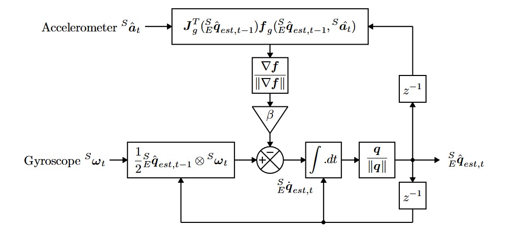
On the other hand, The Madgwick filter employs a quaternion representation of orientation to describe the nature of orientations in three-dimensions and is
not subject to the singularities associated with an Euler angle representation, allowing accelerometer and magnetometer data to be used in an analytically
derived and optimized gradient-descent algorithm to compute the direction of the gyroscope measurement error as a quaternion derivative. Its advantages over
the complimentary filter includes the use of a MARG sensor array, consisting of a magnetometer, accelerometer, and gyroscope, reducing drift and providing more
precise long-term orientation estimates. Additionally, the gradient descent allows for the algorithm to constantly try to converge on the best
solution that minimizes estimation differences from the accelerometer and magnetometer, increasing reliability. Since now we have reliable orientation data,
we can then feed it into our control algorithm to generate responses attempting to stabilize the aircraft
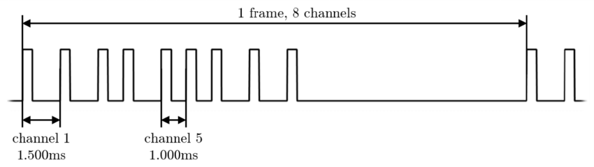
The Mictrocontroller Recieves signals from the radio as PPM(Pulse Position Modulation) signals. These signals encode information by modulating the timing
between signal pulses. Our reciever would encode 8 channels of data, with each channel corresponding to a button or stick on the controller. Our firmware used
interrupts to capture and decode the data in the PPM signal. The intterupt triggered a flag for the microcontroller to convert the recieved channel information
into updated control inputs.
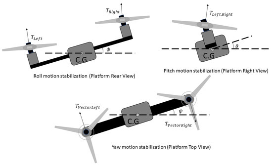
We can control our orientation (pitch, yaw, roll) by altering motor speeds and servo angle. Roll is controlled by increasing one motor speed,
while decreasing the other by the same amount, pitch is controlled by adjusting both servo angles forward or backwards, and yaw is controlled
by adjusting both servo angles in opposite directions. In our control algorithm, we focused on stabilizing pitch and roll, as these axis were
deemed the most unstable. This is in contrast to yaw, which can easily be adjusted by a human pilot once the aircraft is stabilized in other axes.
Our controller uses PID logic for both axes, where our desired state is the angle that is translated from PPM to degrees (taken from the transmitter).
For example, if the pilot wanted to hover, the desired angle would be 0 degrees in both pitch and roll. If there is error in an axes,
it gets fed into the PID loop where an output signal is produced to determine motor speed or servo angle necessary to drive the aircraft to the set point
orientation. For control mixing, even though the system is very non-linear, we would assume for small corrections in a hover, we would be able to linearly
combine pitch and roll corrections together to output. Setting up and running simulations in Simulink was able to prove that this would work well enough for
our case. In order to test this logic we put our Iron Bird prototype into a testing gimble. While this does not perfectly simulate the dynamics of our system
it provided a proof of concept that we could control our system in this way.