Gantry
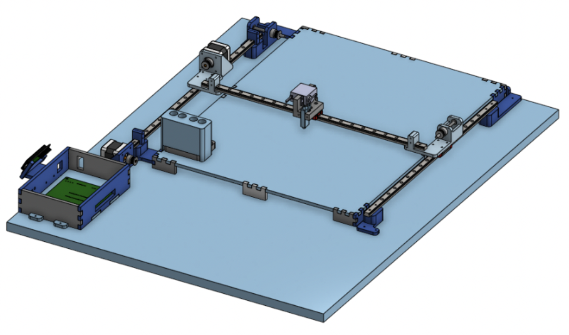
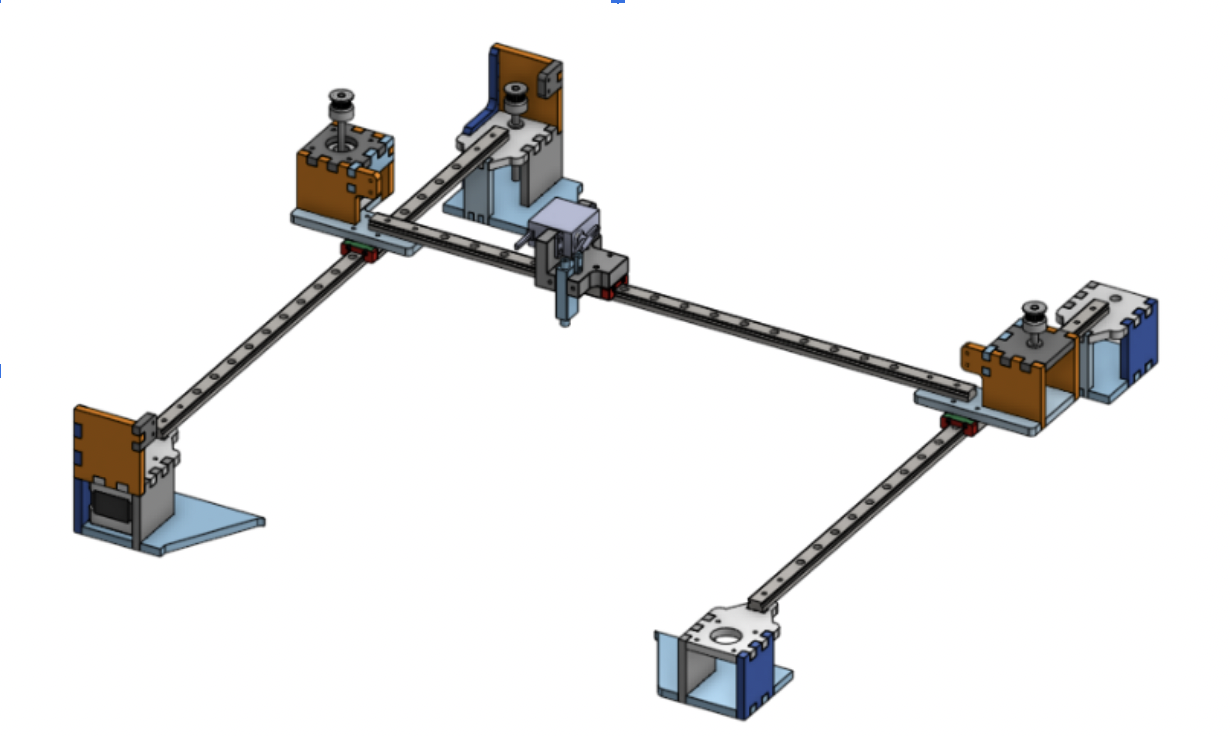
At a high level, our gantry is able to achieve two axes of motion (3 when mounting the end effector, a separate component of the mechanical design for this pick and place) driven by two NEMA 17 stepper motors, two GT2 timing belts (cut to length), and 5mm shaft pulleys to fit on the steppers and opposing end of the driven axes.
Embedded CAD viewer not working? View the gantry assembly in Onshape.
The system is made from 3D printed servo and rail mounts (printing done in-house) using COTS pulleys, belt, shafts, and linear rails with an accessible area of 289 in^2 - enough for an image composed of 1800 candies. The design has the y-axis stepper driving the separate x-axis stepper stage which is mounted on the y-axis linear rails. Belts were fastened to both the x-axis stage and end effector using zip-ties tied through a loop in the stage. Low friction COTS linear rails help achieve smooth, precise motion in both axes at the same time, which is crucial when moving parts as small as bite-sized candy.
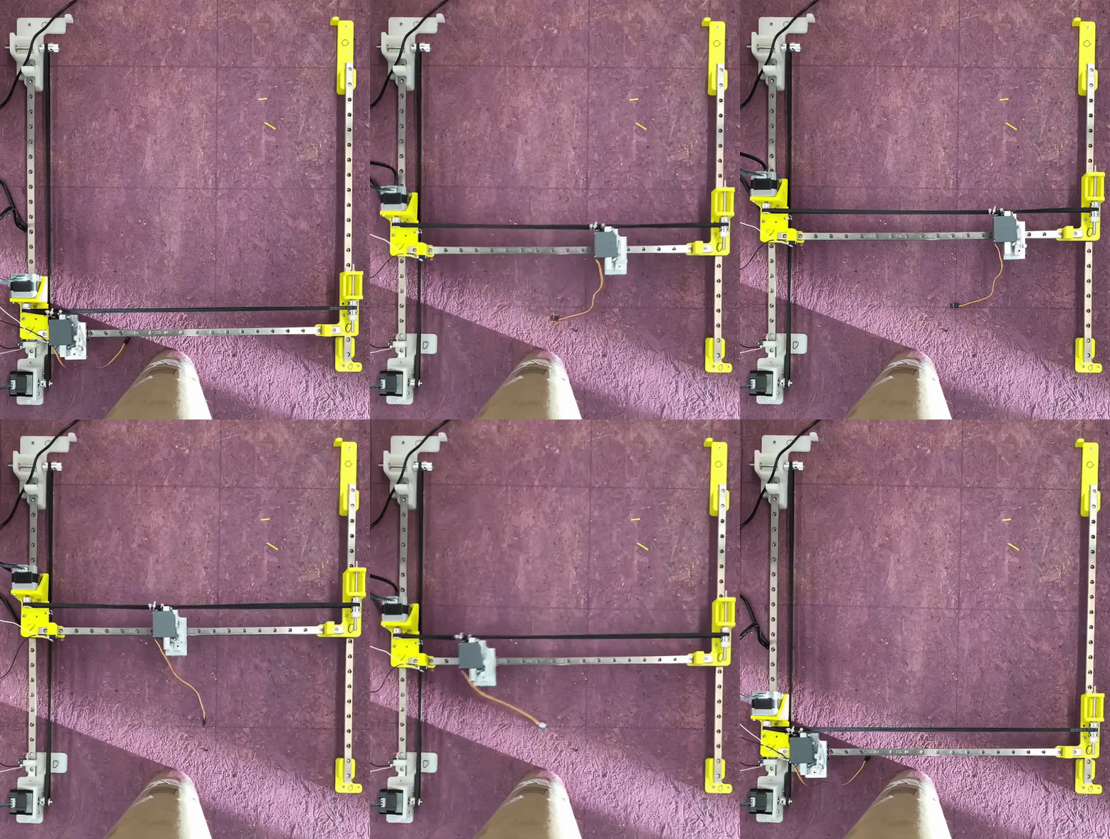
To ensure the end effector would not travel past the linear rails, limit switch mounts and physical material boundaries were integrated in the rail mount design. The whole system was then mounted onto plywood for stability and easier transport around the design studio. Electrical components - limit switches, motors, servos - were all routed to the electronics enclosure housing the PCB located at the front of the machine.
Feeder
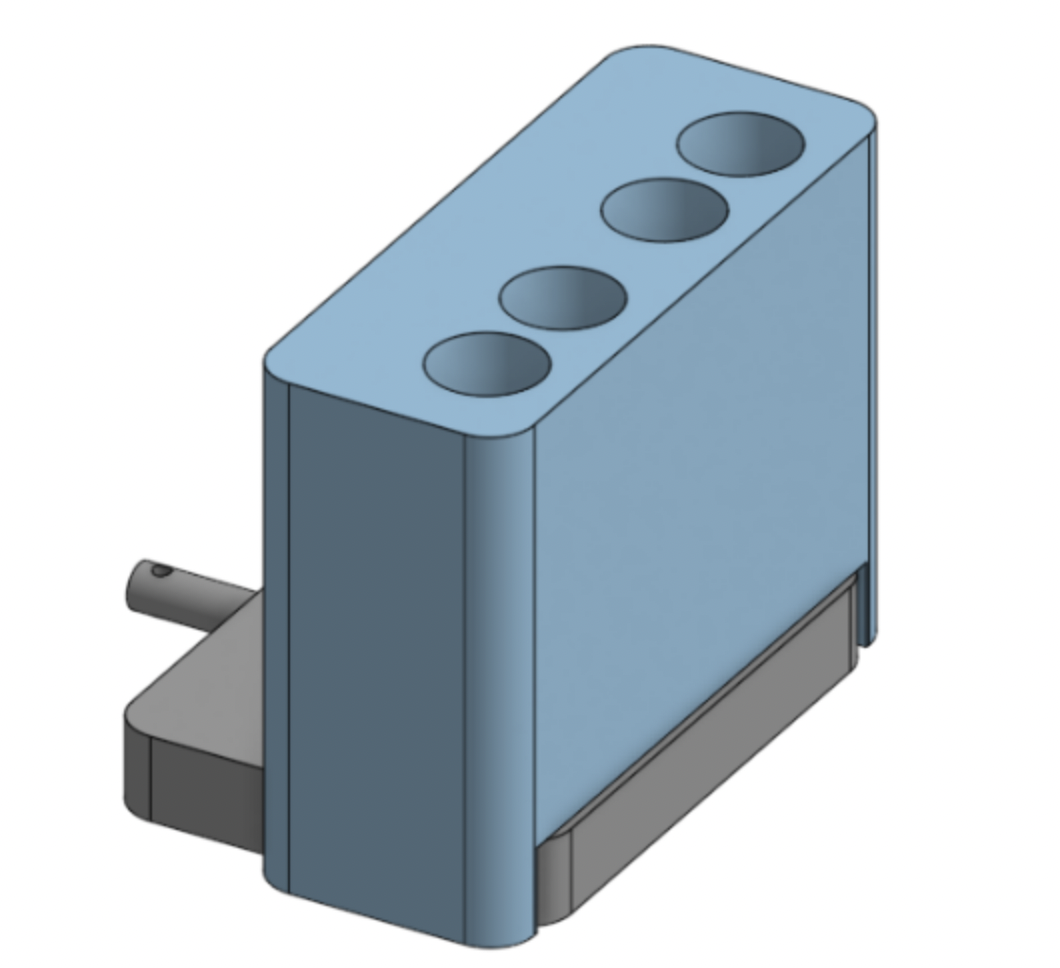
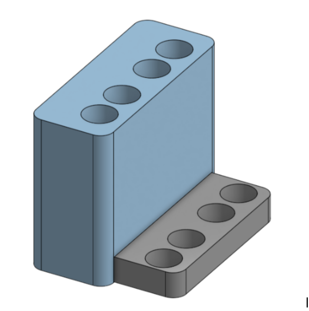
The feeder delivers four separate colors of skittles to the end effector for placement. We needed this mechanism to consistently deliver skittles on demand. We also needed the system to use minimal actuators, as we didn’t want the complexity of adding actuators for each color we planned to use. Our first set of prototypes used no actuators (skittles slid down a slide to be picked up), but we discovered that the skittles’ shape made them jam easily. The current design uses a servo to reload a four-color tray. The skittles are stacked vertically above the tray, which we found lets them travel easily. Skittles can be fed into the top of the reservoirs to refill them during the assembly of large images.
Embedded CAD viewer not working? View the feeder assembly in Onshape.
End Effector
The end effector handles the skittles for placement on the board. It uses a vacuum line, suction cup, and servo to hold skittles and release them when the gantry has arrived at the correct position. This design follows the same scheme as previous prototypes, but incorporates lessons learned from our first sprint. The silicone suction cup allows for secure gripping, the metal surfaces slide smoothly during actuation, and the overall mechanism is much more compact. The end effector bolts to the output carriage on the gantry, and a connected timing belt pulls it along the X axis.
Embedded CAD viewer not working? View the end effector assembly in Onshape.
Next Steps
Given more time, there are some edits to the current design and ways we would like to take the design further. The first edit would be to drive both sides of the x-axis stage - have two steppers driving y-axis motion. This would prevent current problems with too much freedom and inaccuracies on the non-driven y-axis rail.
Another improvement would be to make the design more compact. As it stands the gantry itself cannot necessarily be shrunk, but the plywood that the project currently sits on can be redesigned into a more final enclosure that combines the electronics box and the gantry / bed. The enclosure should also cover the moving parts of the system to prevent any human errors - like bumping - while it is creating the image.
Finding a better way to clamp the belts to the carriages would benefit the performance of the machine as well. There are several elegant timing belt clamps that exist and any number of them would work with the system. That said, the carriages must be designed with these clamping methods in mind to prevent interference issues.

