Process
Our product was developed over three two week sprints.
Sprint 1
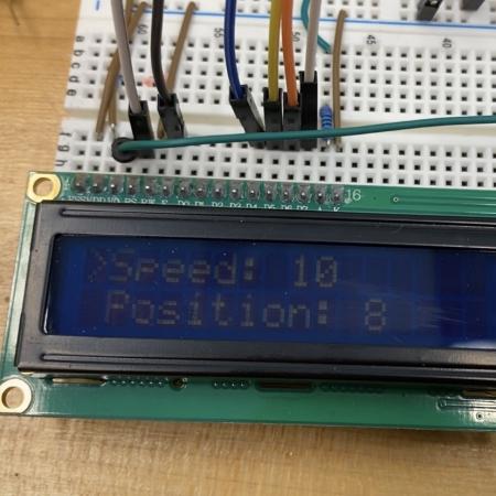 For Sprint 1 the user interface consisted of a 16x2 LCD screen. The screen, which we were able to borrow from another Olin student, was able to display two lines of 16 characters at a time. We used it, along with two push buttons and a dial, to create an interface that could set the speed and distance of our prototype. The push buttons controlled which line was selected and the dial was used to change the settings as well as to start the slider when pushed.
The motor control for Sprint 1 consisted of a simple forward-backward operation of a single stepper motor. The motor moved the gantry across 8 inches of rail. On the firmware side, the Arduino was using a hard-coded square wave generator to step the motor forward at varying speeds. While the speed of travel parameter was adjustable, it was unitless and its range was very limited. Despite significant research into stepper motor drivers, multiple of the drivers’ current limits were exceeded, which may have damaged them.
The Sprint 1 mechanism was exclusively 3D-printed and consisted of a simple pulley system with a slider, connected by a string, on a short piece of 80-20. This worked as a proof-of-concept, however, we knew we would need a more robust mechanism as we started Sprint 2. Some considerations were a leadscrew, a rack and pinion, or, our final decision, a belt gantry.
Sprint 2
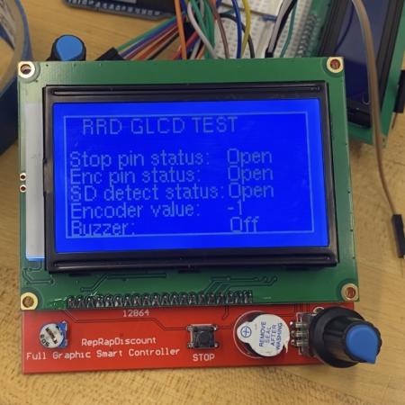 At the beginning of Sprint 2 we bought a 128x64 LCD screen for a few bucks off another team. What we didn’t realize was that this screen came without sufficient documentation. This meant that when we encountered an error where the dial would skip around or not recognize turns when connected to the screen, we couldn’t get enough information to fix it. This wasn’t our only issue with the screen, and despite many hours spent troubleshooting we eventually decided to move on and purchase the (well documented!) touchscreen we used for Sprint 3 and our final product.
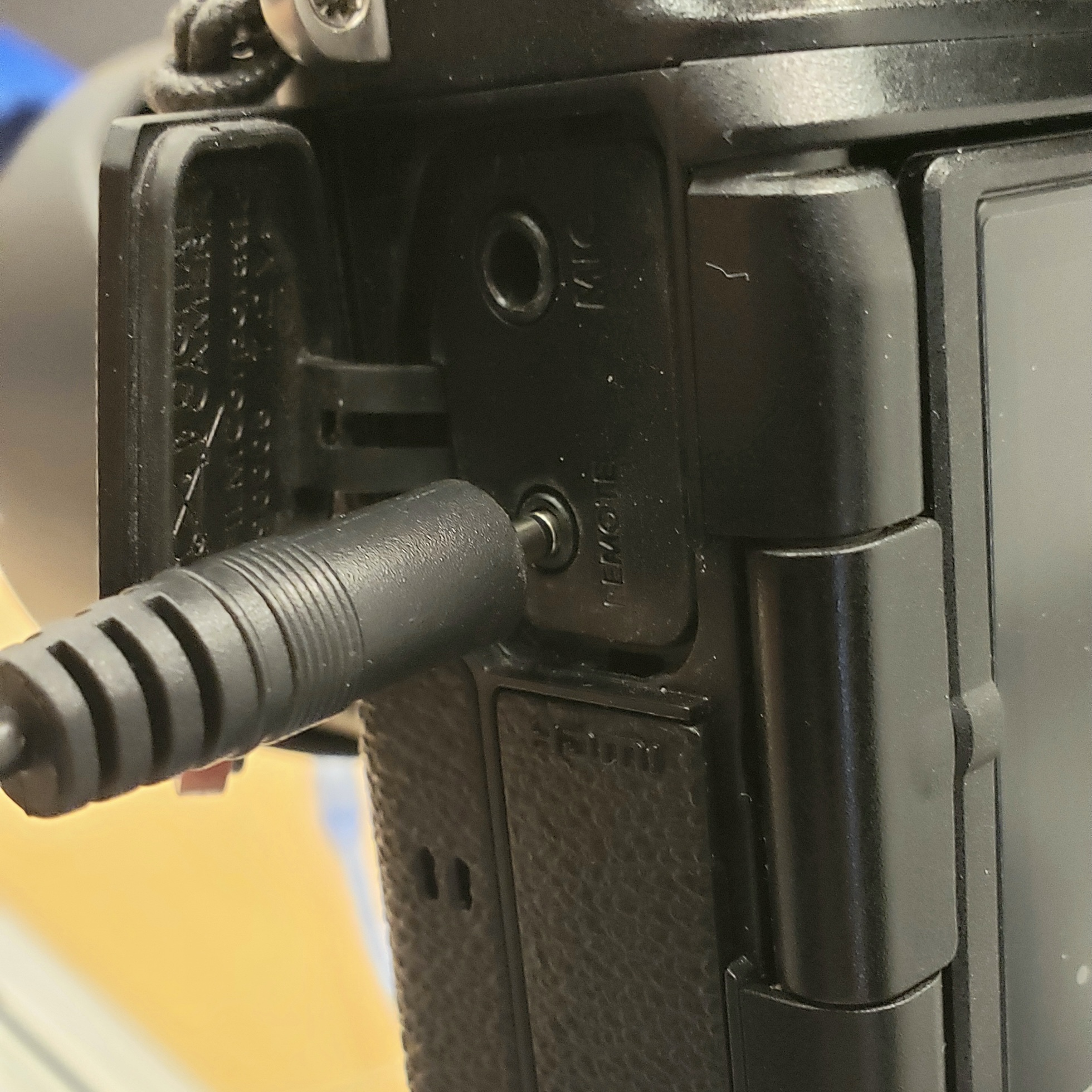 For camera control, we began to look at how other aftermarket shutter releases work to mimic their electronics in our design. We spent an extended amount of time in research for this aspect of the project as it was going to be wired into the camera directly, and we wanted to make sure we were confident in what we were doing so we didn’t accidentally electrocute an expensive camera. We eventually decided on using an optocoupler and had this system working independent of the rest of the project.
On the motor control front, the code from the first sprint was extended to a full length slider of roughly 5 feet. There was significant experimentation with power supplies, but the same firmware scheme was still in place. The code for the pan mechanism was also implemented, though it was not tested because the pan mechanics were not yet in place.
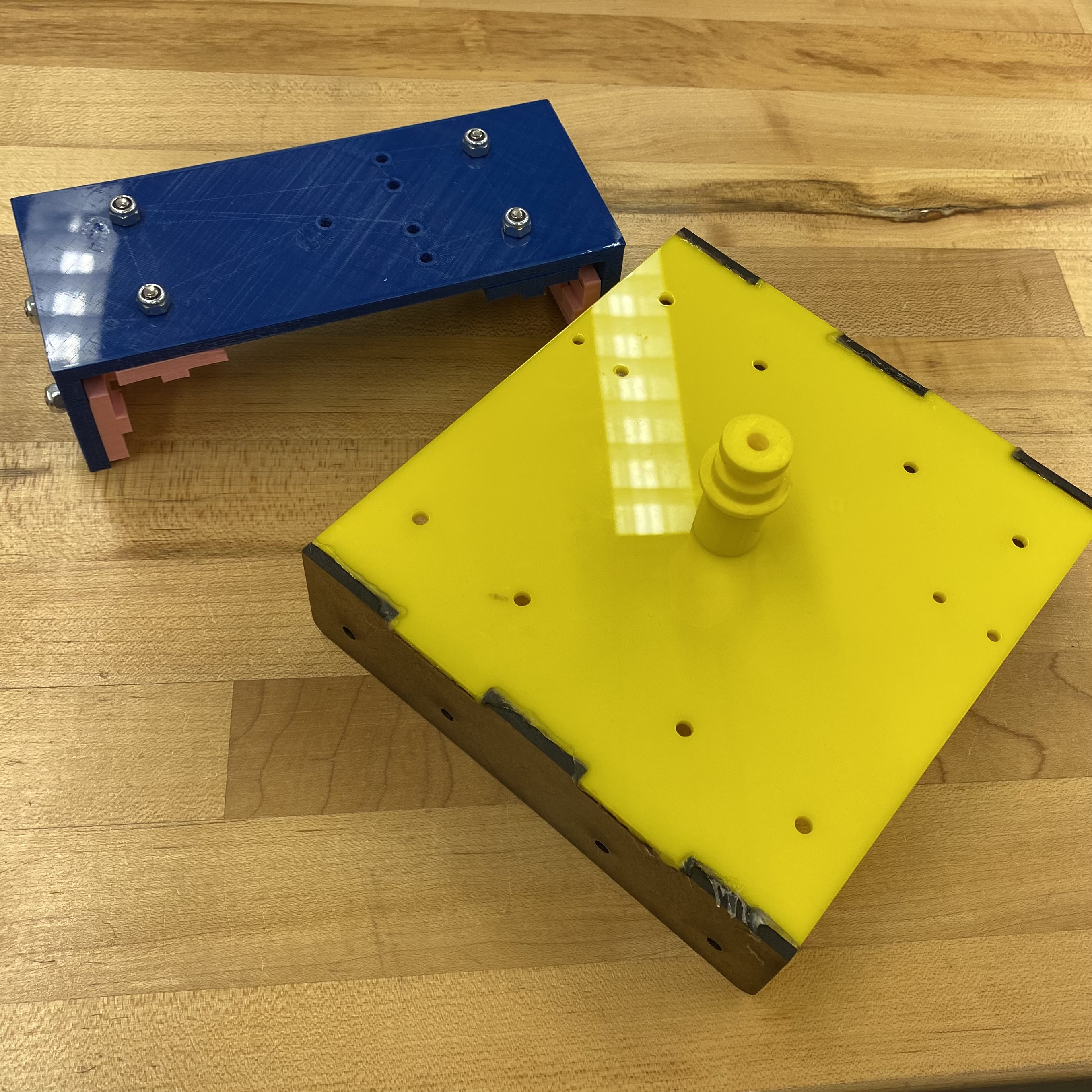 For Sprint 2, the major step we took forward was building the frame and rail assembly. After Sprint 1 we decided to stick with 8020 for our rail since it seemed to work well enough and it provided structural rigidity. We took 2 pieces of 5 foot long 8020 and used some aluminum brackets we plasma cut to brace them. All the other pieces were still mostly 3D printed, however, we had a belt mechanism with simple gear belt pulley mounts at either end instead of the string mechanism. These were a little unstable and could twist causing increased friction. The overall mechanism worked, although was not as smooth-moving/stable as we envisioned for the final stretch goal project. There was high friction with the 3D printed bearings that rubbed against the 8020 rails. This mechanism also did not have a pan function, but it had a mount for the camera. We took the head of a tripod and designed a 3D printed piece to mount the head to.
Sprint 3
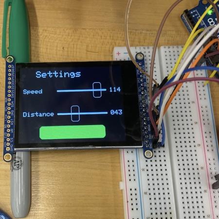 We began Sprint 3 with an Adafruit 2.8” TFT capacitive touchscreen. While we did have much better documentation, we still struggled with switching between the different screens (intro, settings, etc.) that we wanted on the user interface. We initially attempted a switch...case technique in Arduino, but realized that this was leading to “double tap” requirements and other refreshing glitches. Thus, we simplified our code to have a variable (‘wscreen’) which had a numerical value corresponding to each screen, effectively bypassing the switch...case requirement in the void loop.
 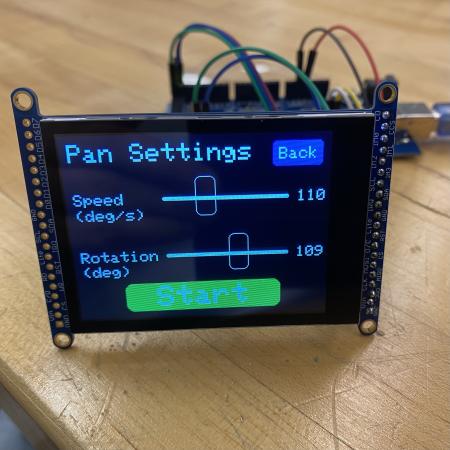 We also had some difficulty finding support for sliders (which we use heavily in our settings screens). We were able to find a tutorial code, but it had the incorrect orientation and required a lot of manipulation to integrate with our preexisting code. We were ultimately able to create a 5-screen UI, with single-tap response and functional (customized) sliders, which retain values throughout the sliders motion to maximize functionality and allow for quick iteration.
Sprint 3 came with a variety of successes paired with their own issues. Switching stepper control to the SpeedyStepper library greatly increased the smoothness and the versatility of the motors. Introducing microstepping also quieted down the motors and helped with torque issues. However, the circuitry’s complexity increased by an order of magnitude. Adding in a second motor driver meant designing the system so that it could supply proper current to both motors. Along the way to adjusting the current limits through each driver, at some point the drivers lost their function. Without much insight into the insides of the drivers, the electrical progress stalled. Integration with the UI team, which wa suppose to happen at the end of Sprint 3, was pushed to after Sprint 3 and before demo day since without the circuitry working to test the motors, function cannot be validated. Minutes before the live review and demo, the driver completely stopped functioning. Further investigation into this problem was underway at the end of this sprint.
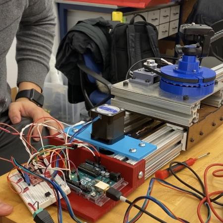 The mechanism further developed in Sprint 3 with re-envisioned mounts for the gear belt pulleys that connected to two sides of the 80-20 for added stability. We upgraded from 3D-printed sliders to low-friction ones from McMaster-Carr, and developed a camera mount from hardboard. Additionally, we developed a pan mechanism, which has a 180-degree range of motion.
Some mechanical finishing work was also done such as designing and fabricating mounts for the arduino, breadboard, and touchscreen to mount them to the camera slider. These parts were designed to fit onto the end of the product in such a way that they don’t reduce the total travel along the linear rail.
Bloopers
This project came with some great successes and a lot of failures. Take a look at some of our camera slider fails below.