Our electrical system consists of two main sub-assemblies. The first is the circuitry that is required to run 15 servos and the second is to spin the winding gear. The main reason for having two exclusive electrical systems is due to the way our Arduino code runs the servos. It is more complex to create firmware that continuously runs a motor that is split up by case statements so we created a separate sub-system for it.
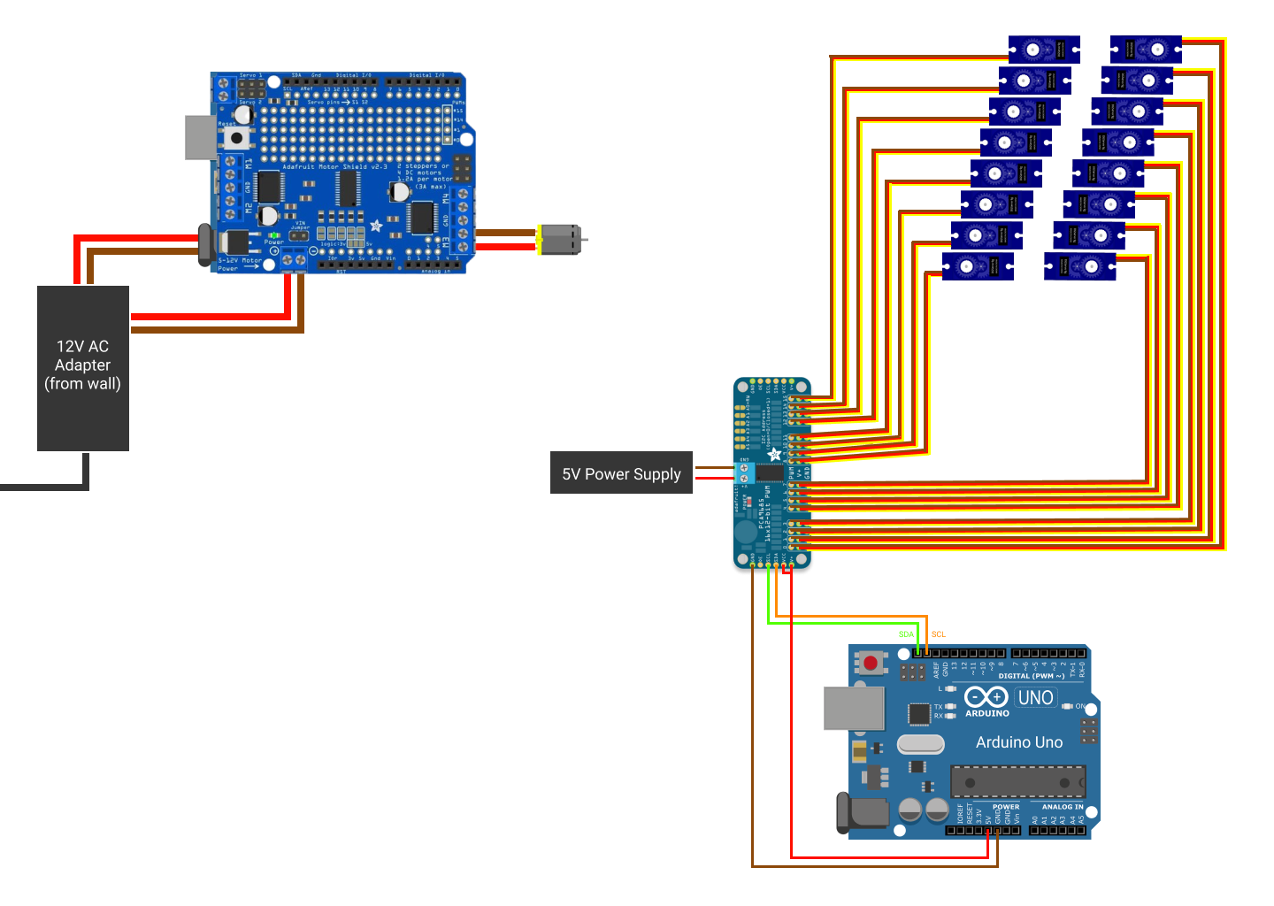
Here we have the electrical components of our project. The Arduino with the motor shield above is used to power the motor that spins the music box gears. The Arduino to the right receives serial communication from the laptop and moves the servos.
This sub-assembly main components are an Arduino, an Adafruit motor shield, and a dc motor. Both the Arduino and motor shield are powered by the same 12V AC Power Adapter plugged into the wall. The DC motor is controlled and powered by the motor shield. We are running the motor in only one direction.
This sub-assembly main components are an arduino, the PCA9685 Motor Driver, 15 Micro Servos, and a 5V power supply. Our standard Arduino Uno only has 5 PWM output pins and we wanted the capability to run at least 15 micro servos (that could be extended up to 32 if we wanted). We did some research and found the PCA9685 16 Channel 12-Bit PWM Servo Motor Driver I2C Module for Arduino Robot. Each board allows us to run up to 16 servos and is 5V compliant. In addition, the Adafruit assembly guide advises using a different power supply than the Arduino 5V pin to power your servos. This is because electrical noise and 'brownouts' from excess current draw can cause the Arduino to “act erratically, reset and/or overheat”. Also, when speccing the power supply we had to keep in mind that many servos moving at the same time will need a lot of current. Due to the fact that we are only ever running one micro servo at a time (draws only a few hundred mA), we were able to use a lower current 5V power supply. However, in the future if we wanted to run multiple servos at once it is ideal to have a power supply that can supply at least 2A. In addition, the PCA9685 uses I2C protocol to drive the PWM pins. The main feature of this protocol is the fact that it is very easy to expand and connect another secondary device (we could add a second PCA9685 to control up to 32 servos).
created with
WYSIWYG HTML Editor .