Sprint 3
Since the parasaltic pumps were still not fully implemented, getting the pumps working properly was pretty high on our priority. At the same time, we recognized that the breadboard implementation of the motor driver board was very space inefficient - therefore, we decided to create a solution that would reduce the amount of space taken by the motor drivers and their respective wires. We also attempted to refactor the code to reduce the need for the large hardcoded chunks that control the drink choices; however, we were unable to do so successfully within the time frame.
Mechanical:

This sprint we completely redesigned the pumps from the ground up out of materials that don’t run the risk melting from the temperatures of the motors. Our electrical team utilized the enable / disable pin to further minimize heating on the motors. By redesigning we were able to easily change parts in our modular pump design through the use of rapid prototyping on the laser cutter. We resolved motor shaft engagement by purchasing a machined part that allowed us to connect our central hub to the entire shaft. Furthermore, increased tolerances allowed for more effective use of our ball bearings, further reducing friction. This design allowed us to better pump water through our system.
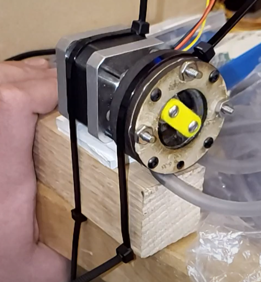
Figure 1: Image of the redesigned pump.
Electrical:
Electrical development narrowed down to two main tasks; finish implementing the power supply that feeds into the arduino, and create a less space intensive solution to the motor driver board.
Step-down Circuitry
We originally intended to implement the step down circuitry entirely from scratch onto the power perfboard initiated in sprint 2. However, due to the unability of getting certain components, we settled on using an LM2596 variable stepdown buck converter. This overall ended up being a safer option since we could tune the voltages to fit best for our system. Thus, we arbitrarily chose to tune the converter to output 8V, which is higher than 5V (meaning that we reduce the risk of undershooting) and lower than 12V (meaning that we reduce the risk of overshooting). Then, it was a matter of connecting the 24V lines to the IN+ and IN- ports of the step-down circuitry, and the OUT+ and OUT- to the OUT terminal of the perfboard. We then connected a barrel jack that would connect the 8V to the arduino MEGA 2560. To see the schematic and the physical connections refer to the power electronics section.
Motor Driver Perfboard
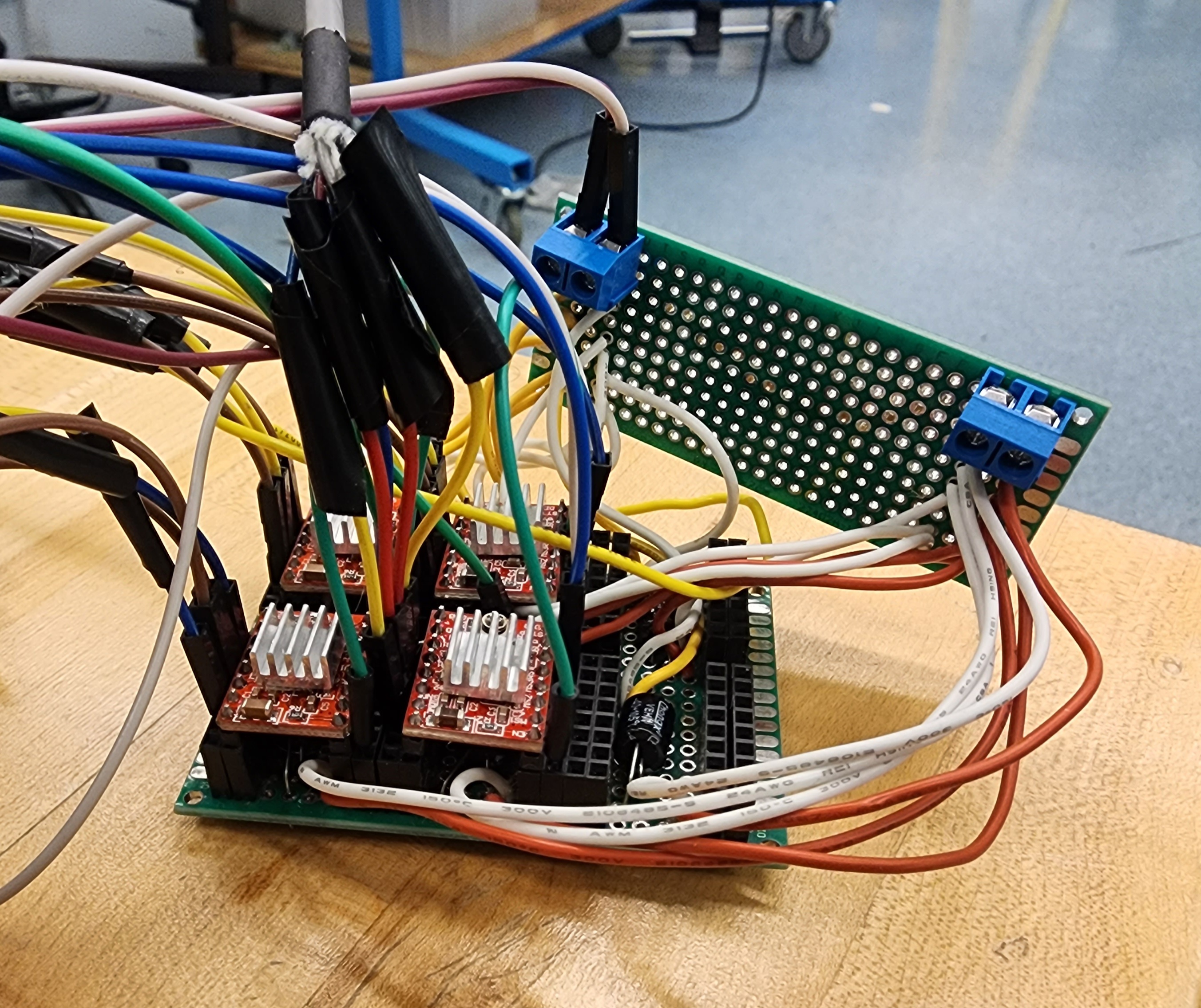
Figure 2: Implemented circuitry of the motor driver board on perfboards.
Originally a reach goal, perfboarding the motor driver board became the next point of focus. The full schematic for the board can be found under the actuation electronics section. Going into sprint 3, we were hoping of allowing our system to accept up to six motors. The perboard reflects this original idea, as it allows up to six A4988 motor drivers. The perfboard implementation meant two things: less wires required, less space taken. Instead of having to deal with an entire breadboard, we were able to use a more condensed design. Also, the power pins are powered by wires directly coming from power terminals. Unfortunately, we cut the wires a little on the short side, making the power board perpendicular to the motor driver board. Regardless, the perfboard allowed us to pack the motor drivers a lot tighter.
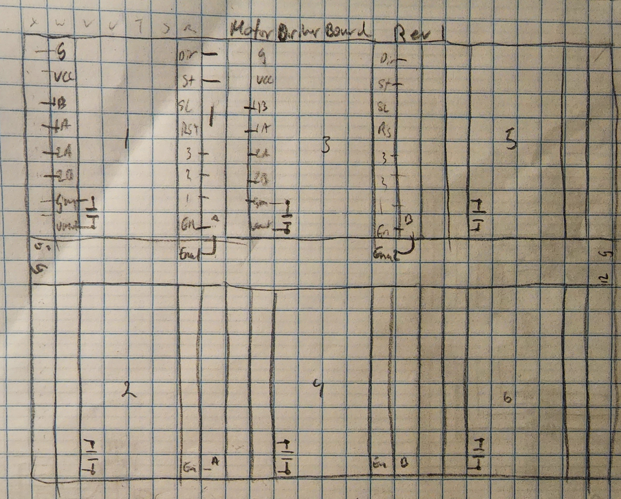
Figure 3: Rough sketch of the perfboardable design where each square represents a usable pin in the perfboard.
Our design allowed a motor driver to work in an 8x8 pin grid, where the 1x8 pin headers connecting to the actual motor driver would have an adjacent block of 1x8 pin headers to recieve the external connections that went to the arduino and the motors themselves. In order to keep the enable and disable functionability, we decided to solder an ena jumper wire that would connect to motor drivers 1 and 3. We could then connect drivers 1 and 2 to the signal ena1, and drivers 3 and 4 to signal ena2. This implementation of the ena connections happened after it was discussed that we would only be using 4 motors for the final iteration. Also note that we are still shorting the sleep and reset pins as directed by earlier tutorials. The following image compares the sizes of the perfoard and the breadboard to prove that the perfboard implementation served its purpose.
Firmware:
Unfortunately, we were unable to accomplish any firmware improvements. We entered sprint 3 having met a lot of our MVP for firmware: functionality. Acknowledging the work left on the pumps, we decided that a satisfactory effort on firmware would be to refactor the blocky code from sprints 1 and 2, and condense it to use arrays that would store the pump durations. This idea seemed very straightforward at first, but we ended up running into several syntax issues as well as logical issues. Thus, there were no real changes made to the firmware. That being said, the refactor could still occur between sprint 3 and demo day - depending on the amount of time available to work on these things.
| Sprint 2 | Sprint 1 |