Sprint 2
The goal for this sprint was to catch up on what was not accomplished in sprint 1 - get liquids flowing from point A to point B through the motors. At the same time, we wanted to expand the capacity of our electronics to work for at least 4 motors. We also decided to add to the finite state machine to allow for both a user mode and a maintainance mode.
Mechanical:
We successfully manufactured the 3D printed pump design and pumped water somewhat consistently. However we ran into additional issues primarily with the tolerances with the pump and our tubing, the central hub continuing to not engage, and high thermals melting the 3d print. We attempted to recreate the central hub but that did not remedy the problem with the central shaft engaging properly. Thus, the pump assembly had a life span of about 5 minutes at most.
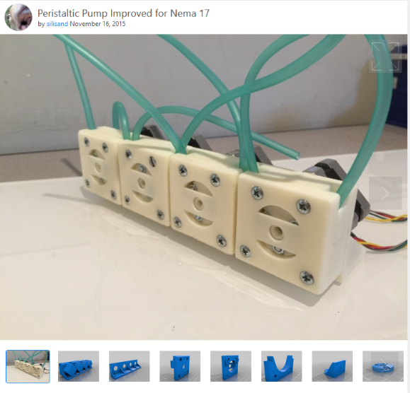
Figure 1: What the pumps were supposed to look like.
Video of the pump assembly pumping water from a glass bottle
Once the pump assembly lifespan expired, it would just make a really loud noise of the shaft rubbing against the assembly, which was only magnified with a new cardboard box casing that was designed for sprint 2.
Electrical:
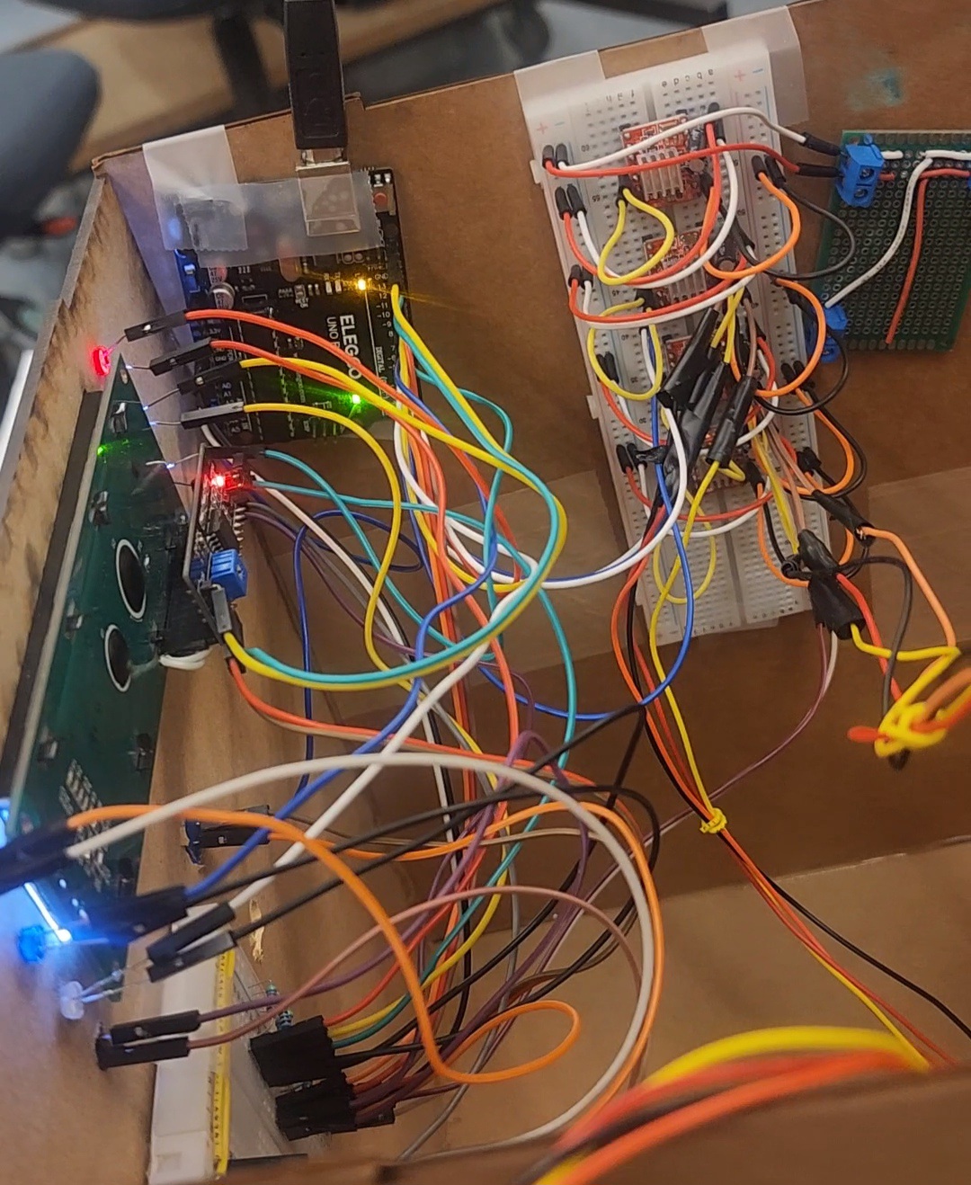
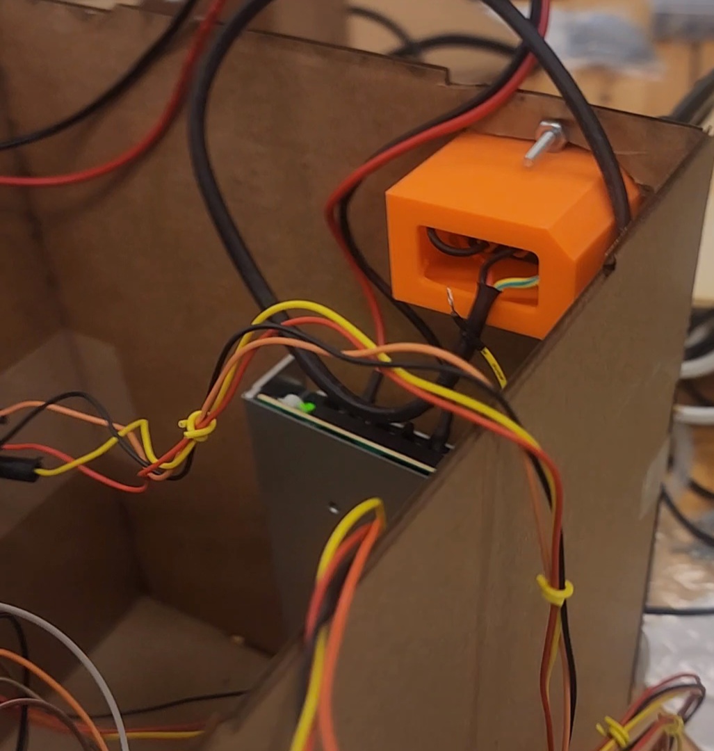 Figures 2 & 3: Integrated electronics in Sprint 2. || Integrated power supply.
The main ground we managed to cover electrically was the expansion of the motor driver board to include the electronics necessary for 4 motors, and the implemenation of a 24V power supply to power the motors. We chose to put off the step down electronics that would allow us to power the arduino from the power supply.
Functional Electronics
The main improvements to the electrical design were strictly functional. This is where we begin to draw the line between power electroics and actuation electronics.
Power Electronics
In terms of power, we were able to implement the 24V power supply that we had scrounged from the 3D printer where we got our motors from. Its implementation was rather straight forward, as it simply involved taking the connections from the 3D printer case, and attatch it to the Barbot. In anticipation for step down voltage, we also created a small protoboard that would split the 24V into 2 pathways - one that would go to the motors, and the other that would go through the step down, and ultimately the Arduino. Since we were unable to implement he step down circuitry in this sprint, the Arduino was still powered by the laptop via the USB connection.
Actuation Electronics
For Sprint 2, we increased the size of our motor board to allow for 4 motor driver. We also chose to get new motor driver modules. Though they were still A4988s, these new ones had a current limiting potentiometer, which is one thing the last motor driver modules lacked. Although the pin out was slightly different, it was still fairly straight forward to implement. We were able to use this website to validate our desgin.
Since we amped up the amount of motors we are using, we have also decided to upgrade our microcontroller from an arduino UNO to an arduino MEGA2560. This upgrade gives us more digital and PWM pins to allow us to control more motors, continue receiving button signals, and continue using LEDs to represent the state.
Firmware:
One of the first firmware updates that occured during sprint 2 was the change from creating the pwm signals using delays to using the AccelStepper library which can be obtained by typing AccelStepper in Arduino IDE. Due to the way that the library works, we begin by setting a target distance arbitrarily high (1000000 steps), and allow the motors to run in the dispensing / clean / set-up towards that target. Whenever we wanted to stop, we would run the .stop() method at roughly 17 seconds before the time the motors actually needed to stop running. We would then “reset” the movement by runnning the .setCurrentPosition(0); method whenever switching out any of these states. More complete notes on the implementation can be found in the firmware subsystems webpage.
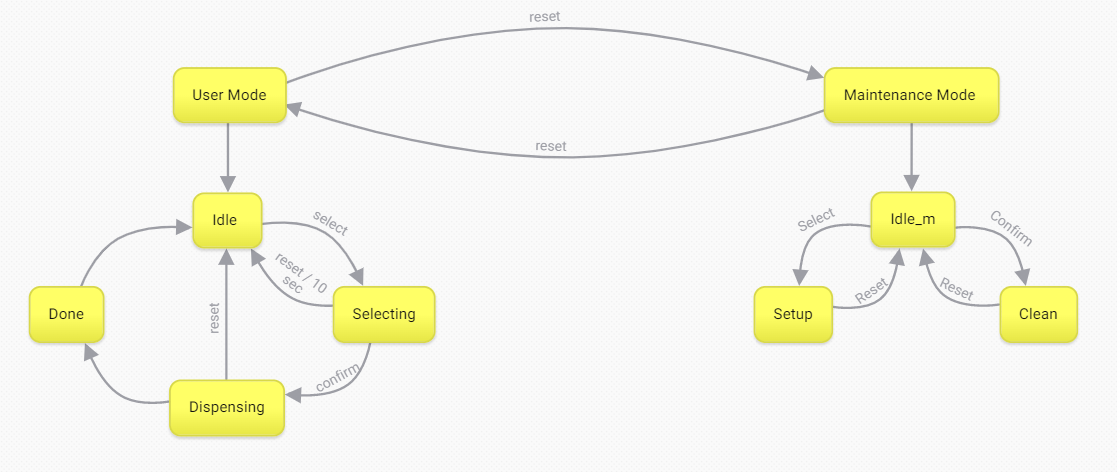
Figure 4: The finite state machine encapsulating both user and maintainance modes
This sprint, we introduced a new mode - maintainance mode. Here we created 2 additional finite state machines: The main finite state machine, and the maintainance mode finite state machine.
Main FSM
The main finite state machine toggles between the user and maintainance mode by pressing the reset button during their respective idle states.
User Mode FSM
The user mode did not change, except that we now made it so that pressing the reset button during the idle state and also implemented the AccelStepper library as stated previously
Maintainance Mode
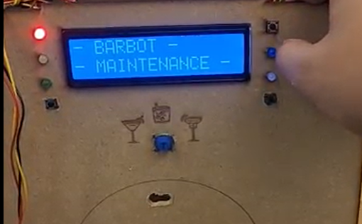
Figure 5: The display when entreing maintainance mode.
This mode exists to add maintainance issues. This state machine allows the person running the barbot to “set” the liquids to the tip of the tubes, and to run a cleaning cycle.
Idle
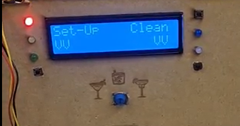
Figure 6: The display while in idle mode
The idle mode here acts the same way as the idle in the user mode, but instead of waiting strictly for the select button, it waits for either select, confrim, or reset buttons. In our design, the select button takes the system to the set-up state, the confirm button takes the system to the clean state, and the reset button takes the system back to the user mode.
Set-Up
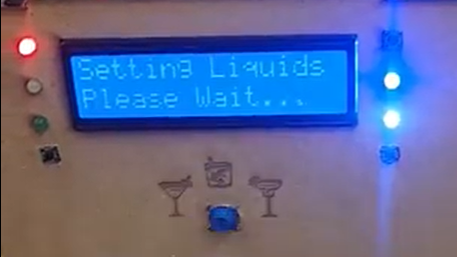
Figure 7: The display as Barbot sets the liquids
The set-up mode is meant to turn on and run the motors for just enough time to allow the liquids to stop at the end of the tubing. Since we did not have the exact length of tubing determined, we were unable to set an actual time parameter for how long the motors should run. This should not be hard to update, as the value is stored in a variable named setupdur (short for “set up duration”).
Clean
Similar to the set up mode, the clean mode is simply in charge of getting all of the motors running at once. The difference being that the clean mode allows the motors to continue running until the arbitrailit high step count is reached. In order to stop cleaning, the user must press the reset button to make it back to the maintainance idle mode.
| Sprint 1 | Sprint 3 |
