Sprint 1
Due to certain complications that made it harder to work on the project as a team, we were unable to get much progress in getting water moving from point A to point B. The original goal for the sprint was to create a mix of two drinks, such that we would use 2 ingredients to create 3 drinks: ingredient 1, ingredient 2, and a blend of ingredients 1 and 2. For this, we wanted to have a rough version of barbot that integrated two motors, their respective pump assemblies, and a way to interface with the system. Unfortunately, a combination of ineffective motor control and lack of functional pump system did not allow us to meet this initial goal.
Mechanical:
We attempted to recreate a used design that was found on thingiverse for the peristaltic pump. We had some problems with the central hub not engaging with the drive shaft on the NEMA 17 motor in addition to not having the necessary hardware to complete the construction of the 3d printed pump.
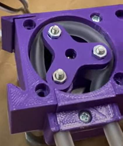
Figure 0.5: An alternate design…
We had an alternate design, noted that these pumps were very high in friction. This combiened with improper motor control led to a pumpless sprint 1.
The casing was pretty much non existant and was created swiftly out of cardboard to hold the working electronics.
Electrical:
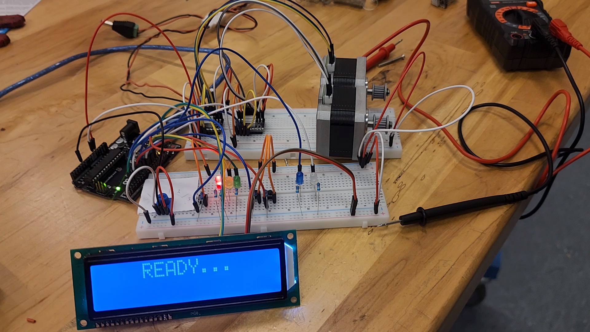 Figure 2: Sprint 1 electronics before being placed in the box
For sprint 1, we were able to accomplish a pretty good leap in the right direction.
We decided to begin powering the system with an arduino UNO which would give us more than enough pins for motors, LEDs, buttons, and our potentiometer.
Functional Electronics
The top breadboard connected the A4988 motor drivers that came with the 3D printer we managed to scrounge. These would control and power the NEMA 17 stepper motors that would actuate our pumps. The motors themselves also came from said 3D printer. We used jumper wires to connect the stepper motors to the motor drivers, which ended up being a not very wise choice since the stepper motor pins were thinner than the connections of our jumper wires. This issue gets assessed in sprint 2.
User Experience ElectronicsS
The middle breadboard contains the electronics designed for user experience. The function of the red, yellow, and green LEDs were to display both the state of the system as well as the drink choice during the selection stage. This idea was generated before the implementation of the LCD screen, which came toward the end of the sprint. Though they are technically an artifact, we argue that it is helpful for the user to have more than one visual cues.
Similarly, the blue and white LEDs were designed to represent the motors running during the dispensing state. This was developed originally to debug the firmware to make sure that the drink selections were correct and that the correct motors would be running at their respective times. As of the end of the sprint, they have remained another feature whose function is mainly controlled by the LCD screen.
The LCD itself was also scrounged from a free cycle pile. The LCD has a SPI controller module that allows us to use SPI to communicate to the LCD screen, using only the SCL and SDA pins of the arduino, instead of the 8 digital pins we would have needed to use otherwise.
The potentiometer was fairly simple, as we just had to connect pin 1 to 5V, pin 3 to GND, and pin 2 to the an analog in port of the arduino.
The exact specs of the resistors used can be found in the electrical subsystem section which did not change throughout the sprint.
Firmware:
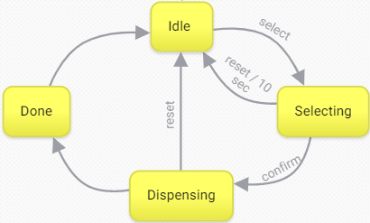
Figure 3: State diagram of the finite state machine implemented
Separating the tasks onto states these four states made it easier to debug the system, since we could then track whether or not the state transitions were occurring when they were supposed to. Note, we also had to use the following LCD library to control the display.
Idle
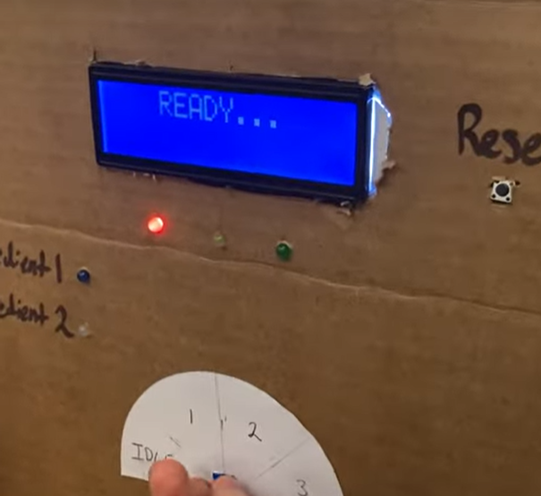
Figure 4: The idle state represented
The idle state is essentialy our default state, and is the state entered at the point of booting up the system. It state tells the user that the system is ready to recieve input from the user. It does so by setting the red LED high, and displaying “READY…” on the LCD screen. During this state, we allow the user to use the potentiometer to dial in their drink choice. It remains in this state infinitely until the “Select” button is pressed.
Selecting
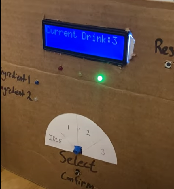
Figure 5: The selecting state represented
When entering the selecting state, we read the potentiometer and perform the necessary calculations to determine the drink choice based on the potentiometer value. Since the analog values range from 0 to 1028, it was just a matter of floor dividing by 257, which would allow us to have drink choices 0, 1, 2, and 3.
By design, we made drink choice 0 an invalid option, which returns the state back to Idle. Though it doesn’t really add to the experience, it makes for another check to make sure that the user is qualified enough to operate the machine.
In this state, we also have a 10 second timer, which is demonstrated by the selection LED blinking every half second. The selection LED essentially represents the drink choice. Again, this was a feature that was implemented before the LCD screen but never removed from this sprint. In figure 5, we see that drink 3 was selected, and thus the green (or third) LED is blinking.
If the user does not press the confirm button, the state reverts back to idle. It will also revert to idle if the user were to press the reset button. This was put in place to allow the user to cancel their choice in case of a wrong selection.
Once the confirm button is pressed, the system then transistions to the dispensing state.
Dispensing
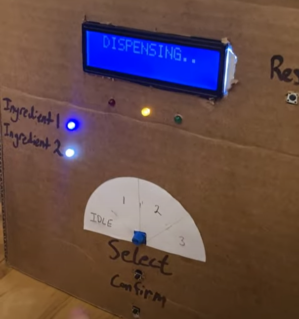
Figure 6: The dispensing state represented
In the dispensing state, we turn on the motors that need to be running. Here, we also turn on the LED(s) that correspond to the motors that are supposed to be running. Also the yellow LED turns on to indicate that we are in the dispensing state.
For this sprint, we attempted to implement the pwm signals that would be powering the motor without using stepper motor libraries, which made for slower and overall weaker performance from the motors. We addressed this issue in the following sprint.
In this state, we can still return to the idle state by pressing the reset button. We implemented this in case of emergencies during the dispensing (ie. the pumps ran out of fluid). This also proved helpful in debugging the system since it allowed us to return idle without having to wait for an entire dispensing cycle.
Once the drinks have finished dispensing, the motors stop driving, and the system transitions to the done state.
Done
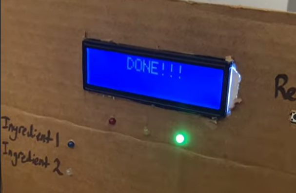
Figure 7: The done state represented
This state can only be accessed when the drinks have finished dispensing. This state will display the words “DONE” and turn on the green LED for 5 seconds, then transition back to the idle state to start the cycle over again.
| Sprint 3 | Sprint 2 |