Electrical Subsytem
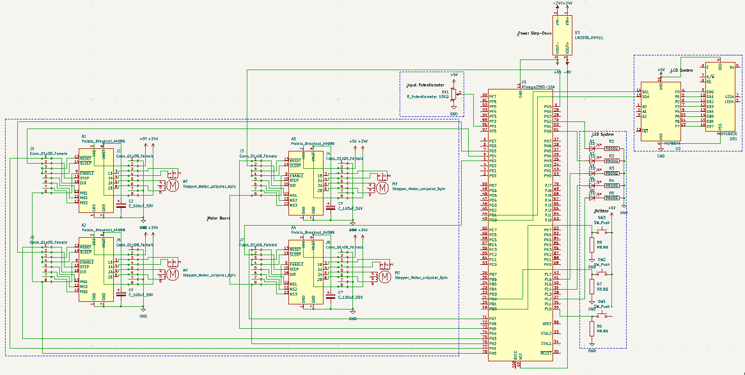
Barbot’s electronics can be divided into two main groups: user experience and functional.
User Experience Electronics
The electronics involved in enhancing the user experience are powered and controlled by an Arduino Mega 2560 microprocessor. The microprocessor and this group of electronics is stored in a compartment isolated from the rest of the action in the following container.
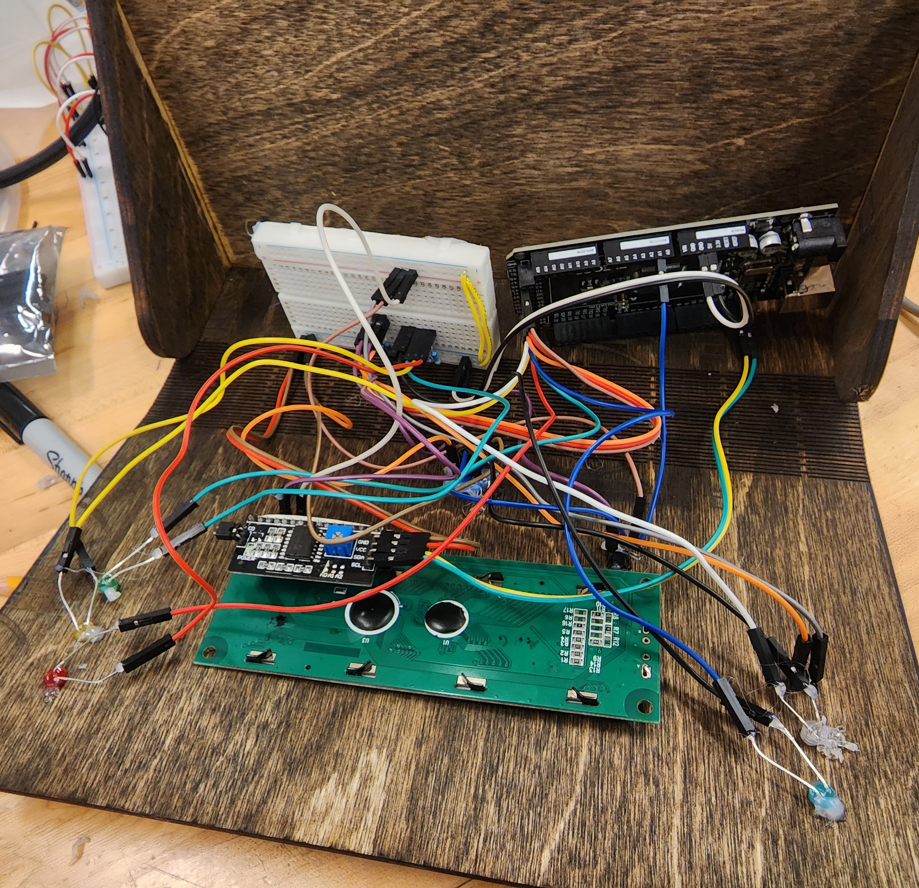 Figure 2: User experience electronics in their compartment
Note, the resistors required to make the LEDs and buttons work are wired on the breadboard, thus fulfilling the schematics found n figure 1 and figure 4.
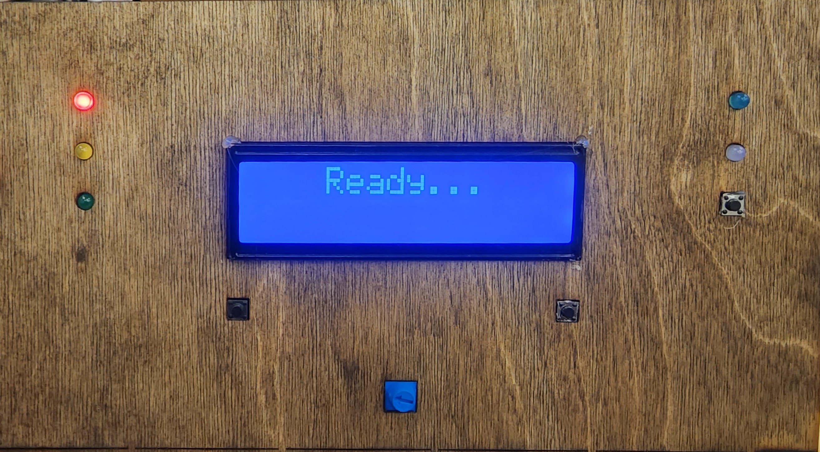 Figure 3: The interface that allows usability.
The red, yellow, and green LEDs here represent the state of the machine. The actual details of what these colors mean when they are on are explained in the Context page under “How Barbot works”.
The blue and white LEDs represent a set of drinks that are being dispensed. These are more artiacts of the two-motor prototype of the barbot, where they once turned on to show which ingredient was being dispensed.
Barbot makes use of three buttons - select, confirm, and reset. The full detail on the functionality of these buttons is explained in the Context page under “How Barbot works”

Figure 4: Schematic of the UX electronics above.
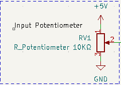
Figure 5: 10KΩ potentiometer used for user input
Despite being a very small schematic, the potentiometer is what allows the user to chose what beverage to get from the Barbot, and is thus a very crucial bit to our system.
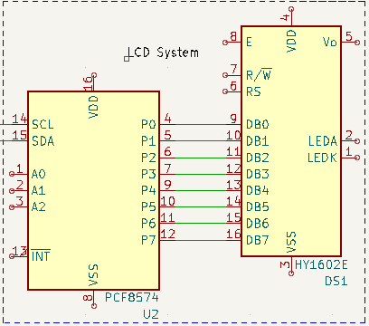
Figure 6: Our LCD system
We were able to scrounge an LCD screen that used an external chip to communicate to the Arduino through SPI. This simplified our electronics since we only needed to use the 2 SCL and SDA pins to connect the display to the Arduino. As per the schematic the SPI Controller is a PCF8574 and connects to the 8 digital pins of the LCD screen, which in our case was a HY1602E.
Functional Electronics
Within functional electronics we have two main systems: power and actuation.
Power Electronics
The power that feeds the Barbot comes from a 24V Power Supply; we use a DPS-320AB-1A that supplies 24V at 13.33A, which is plenty for our applications.`We were able to hook this power supply to the wall using an IEC320 connection.
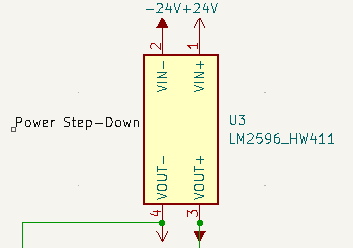
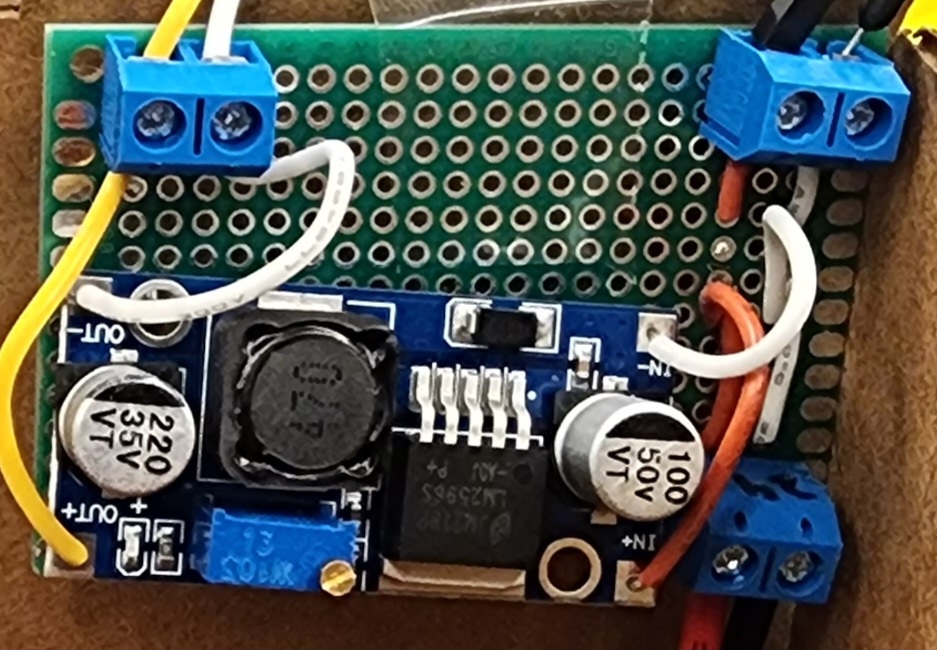 Figures 7 & 8: 24V to 8V step down circuitry
Since we also need to power the Arduino, we divide the 24V current into a 24V path that eventually powers the stepper motors, and another path that goes through a LM2596 variable step-down buck converter to bring the voltage down to 8V. Here, the red wire is the 24V line, and the yellow wire is the 8V line. The choice for 8V was somewhat arbitrary, since we did not want to entirely underpower nor overpower the Arduino, where 5V and 12V are the low and high ranges for acceptable voltages the Arduinos can handle. The Arduino is powered by these 8V through a barrel jack that hooks into the Arduino.
The majority of the electronics run on 5V, thus the remaining power is supplied by the Arduino and distributed by using the breadboard power rails.
Actuation Electronics
In order to power and control our stepper motors, we need to use motor driver modules. We decided to use A4988 due to their low price and general efficacy. Specifically, we used these A4988 which costed us only $10.38 for a 5 pack. Based on the pinouts we drew out the following schematic to design a compact motor driver board.
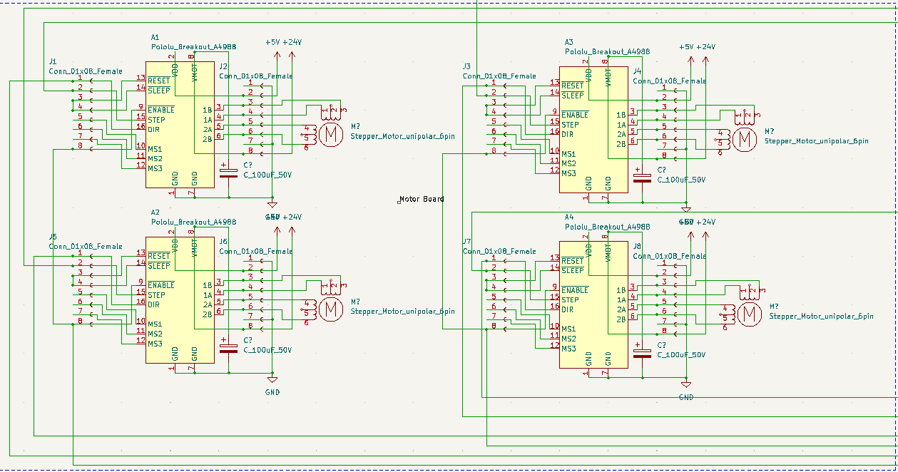
The design features 4 motor drivers that connect to the Arduino via direction, step, and enable pins. Note, the enable pins are active low, meaning that they are on (enabled) whenever there isn’t a signal written to the enable. Therefore, to turn them off means sending a high signal to the enable. The other two pins going to the are handled by the AccelStepper library. The 1a, 1b, 2a, 2b pins connect straight to the motors. The motors recive their 24V through the VMot terminal of the module, which is protected by a 100uF 50V electrolytic capacitor. The VDD is satisfied by the 5V proided from the Arduino.
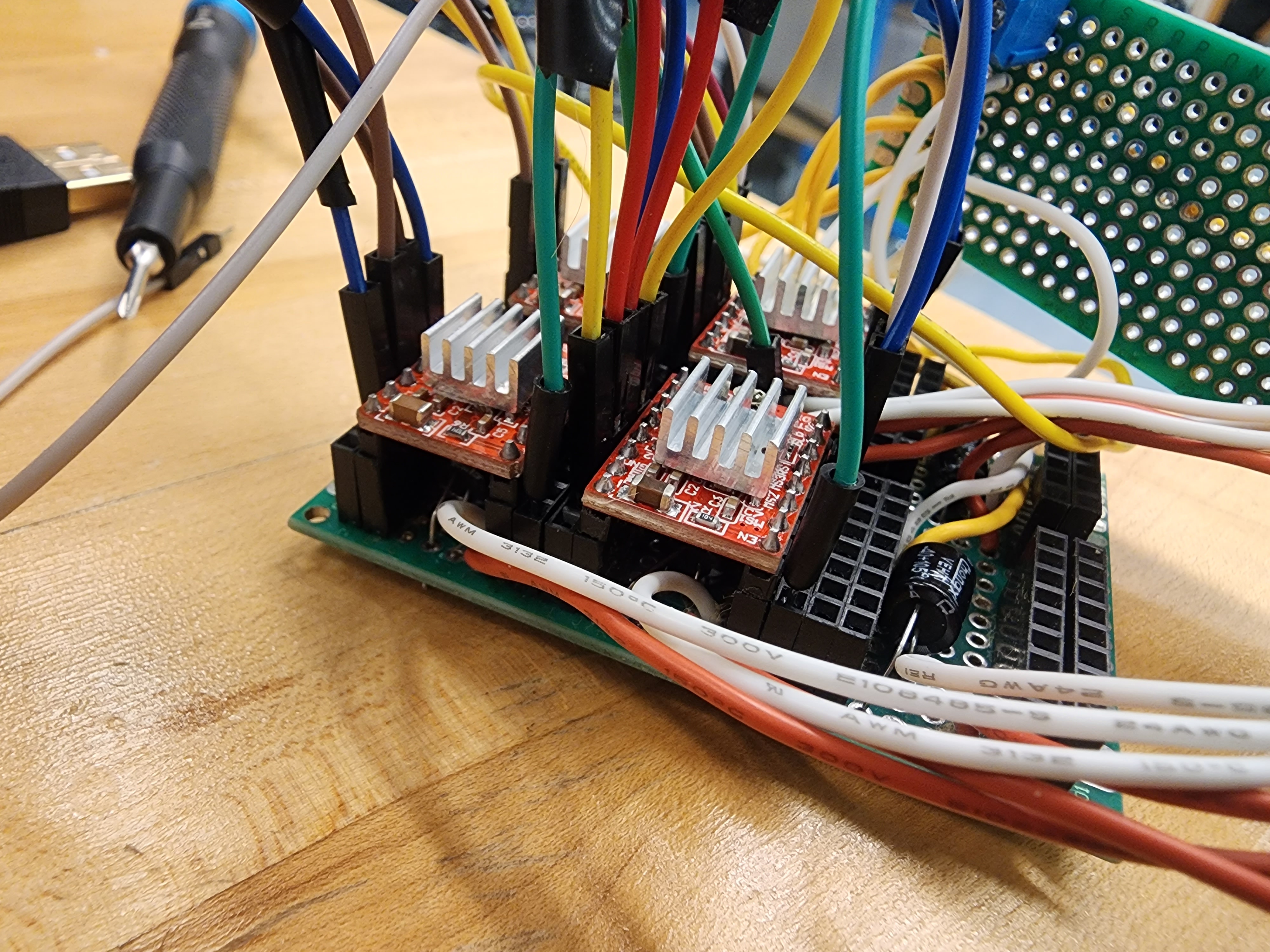 Figure 10: Protoboard of Motor Board circuitry
Originally, we were expecting to handle up to 6 motors, hence why the actual protoboard has enough room to fit 6 motor drivers. Important to note, I used 1x8 pin headers which was very tedious to hold in place and solder. Another caution is that you will need to solder on jumper wires for the enables. Using this design, an enable jumper wire soldered in the middle of the board can be shorted to the bottom right pin of the motor driver. Then, a jumper cable can connect the two ena pinouts.
It is worth noting that I used a separate perfboard to hould the power terminals. This was only done due to the smaller size of the perfboards.
One last note, make sure that the 5V ground and the 24V ground are connected (ideally in a copper pool). Not doing so may cause an overdraw in current since the grounds may be referenced differently.
| Mechanical | Firmware |
