Firmware Subsytem
Barbot’s firmware is designed to handle both the UI electronics as well as the motor functions. We designed Barbot to have two modes: user and maintainance. These two modes are finite state machines that are linked by a main state machine that switches between the two with the press of the reset button.
Source Code:
Firmware Directory
-
Dependencies
Our firmware design takes advantage of the following library dependencies.
-
AccelStepper (downloadable from Arduino IDE)(documentation)
-
LiquidCrystal_I2C (download from GitHub)
The following lines of code take care of including these libraries in our code.
// Stepper Motor Library
#include <AccelStepper.h>
// Libraries for User Interface (i2c LCD)
#include <Wire.h>
#include <LiquidCrystal_I2C.h>

// User interface setup
LiquidCrystal_I2C lcd(0x26,16,3);
Definition of Variables
Our code creates and uses a lot of variables. The first major set of variables define pin numbers. These values are simply how we chose to wire our connections to the arduino.
// State LEDs
const int RED = 39;
const int YELLOW = 41;
const int GREEN = 43;
// Mode LEDs
const int BLUE = 45;
const int WHITE = 47;
// Pump Motors (4)
const int dirPin = 23;
const int stepPin = 2;
const int dir2Pin = 25;
const int step2Pin = 3;
const int dir3Pin = 25;
const int step3Pin = 4;
const int dir4Pin = 27;
const int step4Pin = 5;
...
//motor driver enables
const int ena1 = 22;
const int ena2 = 24;
// Buttons
const int SELECT = 49;
const int CONFIRM = 51;
const int RESET = 53;
// Selection Potentiometer
const int POTSELECT = 1;
Note that the stepPins need to be PWM, and that the POTSELECT pin must be analog. The rest can be any digital pins on the board.
The next variables determine the performance of the motors.
// Motor Parameters
const int max_speed = 800;
const int acceleration = 400;
const int mit = 1;
const int decel_time = (max_speed / acceleration)*1000;
Due to how the AccelStepper library works, we are choosing to determine the amount the motor spins by its duration. decel_time is a parameter that is calculated based on the acceleration and the speed it would be decelarating from in milliseconds. This time sets the lower limit on how long a pump must run in order to be on. With the current max speed and acceleration, the deceleration time is of roughly 2000 milliseconds (2 seconds). Therefore, the motors must told to run for more than 2000 milliseconds. The “why” to this issue gets explained in the dispensing section.
The mit stands for the “motor inteface type”, which accordiing to the documentation, must be set to 1 if we are using a motor driver.
The following block of code is used to define and hardcode the drinks that would be dispensed. The latter end of the code sets the time for the cleaning and set-up functions. In this case, 12 seconds to set the tubes from empty to full, and 90 seconds to clean the tubes.
// Lists of Drink Strings
const int num_of_drinks = 8;
const int num_of_motors = 4;
const char* drink_list[num_of_drinks] = {
  "NULL","Soda Water","Citrus Gin","Herbal Gin","Citrus Gin Soda","Herbal Gin Soda","Citrus Bee's Knees","Herbal Bee's Knees"
  };
long drink_array[num_of_drinks][num_of_motors] = {
  {0,0,0,0},{40000,0,0,0},{0,20000,0,0},{0,0,10000,0},{45000,20000,0,0},{45000,0,10000,0},{0,20000,0,20000},{0,0,10000,20000}
};
long pump_durs[num_of_motors];
...
// Pump durations during setup mode
long int cleandur = 90000;
long int setupdur = 12000;
Since a lot of the Barbot’s functions are time dependent, we must declare these times
// State timings
uint32_t blink_time;
uint32_t dispense_time;
uint16_t BLINK_INT = 500;
uint32_t sel_time;
uint16_t sel_count;
uint32_t dis_time;
uint16_t dis_count;
// Maintainance timings
uint32_t clean_time;
uint32_t setup_time;
We need to also declare the variables that we will use to set the drink choice,
// Choice instantiation
int temp_choice;
int temp_choice_raw;
int new_temp_choice;
int new_temp_choice_raw;
int choice_raw;
int drink_choice;
And initialize the pumps.
// pump initialization
AccelStepper pump1 = AccelStepper(mit, stepPin, dirPin);
AccelStepper pump2 = AccelStepper(mit, step2Pin, dir2Pin);
AccelStepper pump3 = AccelStepper(mit, step3Pin, dir3Pin);
AccelStepper pump4 = AccelStepper(mit, step4Pin, dir4Pin);
The last block of definitions are to create the finite state machine states.
// user FSM states
enum use_states{
  NONE,
  READY,
  SELECTING,
  DISPENSING,
  DONE
};
use_states prior_state, state;

// mode states
enum modes{
  OFF,
  USER,
  SETUP
};
modes prior_mode, mode;

// setup FSM states
enum set_states{
  NOTSET,
  DISABLED,
  CLEAN,
  SET
};
set_states prev_state, curr_state;
The NONE, OFF, and NOTSET states exist to serve as pseudo-states that allow state initialization when entering the idle modes.
Set Up
The code in the void setup() block actually sets up the LEDs and enable signals as output signals,
  // LCD/LED setup
  pinMode(RED, OUTPUT);
  pinMode(YELLOW, OUTPUT);
  pinMode(GREEN, OUTPUT);
  pinMode(BLUE, OUTPUT);
  pinMode(WHITE, OUTPUT);
  digitalWrite(RED, HIGH);
  digitalWrite(YELLOW, LOW);
  digitalWrite(GREEN, LOW);
  digitalWrite(BLUE, LOW);
  digitalWrite(WHITE, LOW);
the potentiometer and buttons as input signals,
  // Button Setup
  pinMode(SELECT, INPUT);
  pinMode(CONFIRM, INPUT);
  pinMode(RESET, INPUT);
  pinMode(POTSELECT, INPUT);
initializes the LCD,
  lcd.begin();
  lcd.backlight();
sets up the states,
  //FSM setup
  prior_state = NONE;
  state = READY;
  prior_mode = OFF;
  mode = USER;
  prev_state = NOTSET;
  curr_state = DISABLED;
and sets the motor performances.
  pump1.setMaxSpeed(max_speed);
  pump1.setAcceleration(acceleration);
  pump1.setSpeed(400);
  pump2.setMaxSpeed(max_speed);
  pump2.setAcceleration(acceleration);
  pump2.setSpeed(400);
  pump3.setMaxSpeed(max_speed);
  pump3.setAcceleration(acceleration);
  pump3.setSpeed(400);
  pump4.setMaxSpeed(max_speed);
  pump4.setAcceleration(acceleration);
  pump4.setSpeed(400);
Finite State Machines
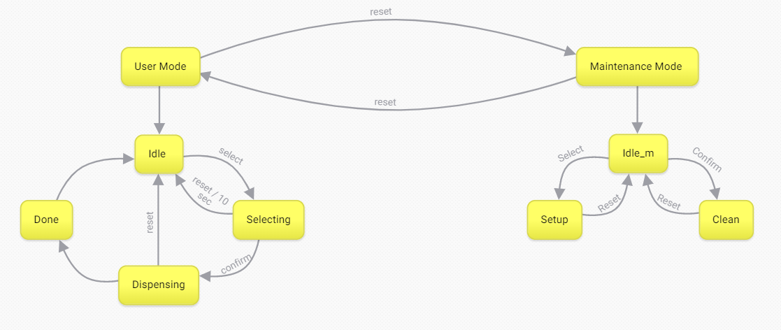
The actual finite state machines live in the void loop() function to run indefinitely.
  switch(mode){
    case USER:
      switch(state){
        case READY:
        idle();
        break;
        case SELECTING:
        selecting();
        break;
        case DISPENSING:
        dispensing();
        break;
        case DONE:
        done();
        break;
      }
    break;
    case SETUP:
      switch(curr_state){
        case DISABLED:
        disabled();
        break;
        case CLEAN:
        clean();
        break;
        case SET:
        set();
        break;
      }
    break;
  }
There are two modes: a user mode and a maintainance mode. Within each mode, we have nested a finite state machine that take care of how the modes should function. The following sections will explain the contents of each function.
User Mode
The user mode is booted by default. Here, the user will be able to select and confirm a drink out of a selection of hardcoded drinks, and recieve the drink mixture dispensed right out of the nozzle.
    case USER:
      switch(state){
        case READY:
        idle();
        break;
        case SELECTING:
        selecting();
        break;
        case DISPENSING:
        dispensing();
        break;
        case DONE:
        done();
        break;
      }
    break;
idle() || selecting() || dispensing() || done()
Idle
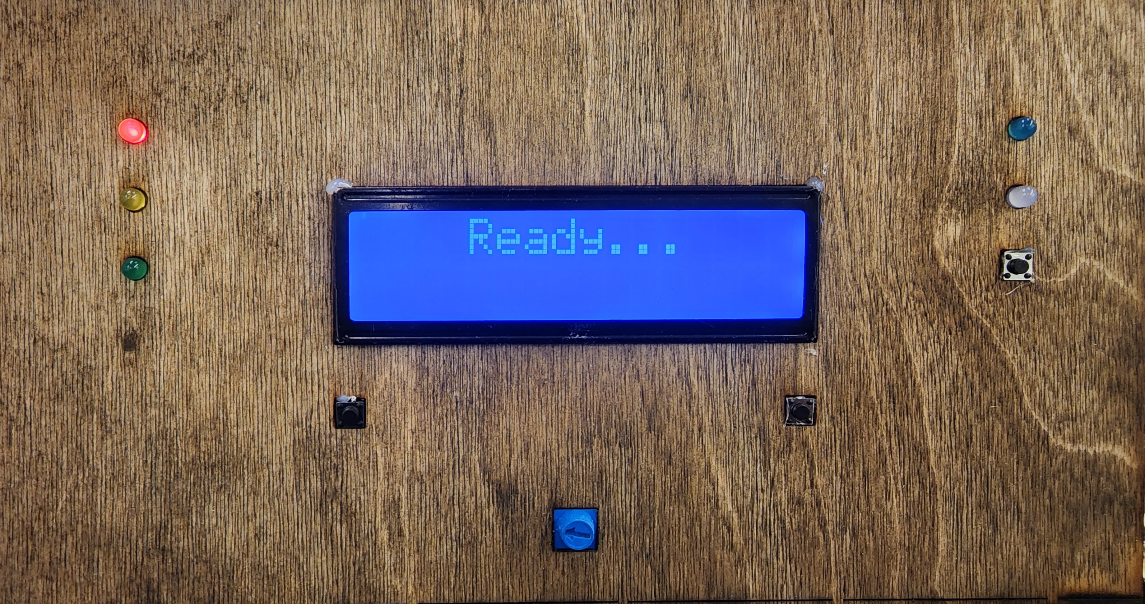 Figure 2: UI during the idle state
When entering the idle state, we turn on the red LED that indicates that its ready to get user input, and the blue LED that indicates that its in the user mode. We also disable the motor drivers to avoid heating up the motors while idling.
void idle(){
  // Wait for the SELECT button press, in the meantime, hold RED on.
  if (state != prior_state){
    prior_state = state;
    digitalWrite(RED, HIGH);
    digitalWrite(BLUE, HIGH);
    lcd.setCursor(4,0);
    lcd.print("Ready...");
    digitalWrite(ena1, HIGH);
    digitalWrite(ena2, HIGH);
    temp_choice_raw = analogRead(POTSELECT);
    temp_choice = temp_choice_raw/((1028/num_of_drinks) + 1);
    lcd.setCursor(0,1);
    lcd.print(drink_list[temp_choice]);
  }
The temp_choice_raw and temp_choice are used to display the drink that is being referenced by the potentiometer. This was a suggestion given to us by one of our peers, which greatly facilitates the drink selection. Below is the code that allows Barbot to continuously if the potentiometer changes to a different drink.
  new_temp_choice_raw = analogRead(POTSELECT);
  new_temp_choice = new_temp_choice_raw/((1028/num_of_drinks) + 1);
  if(new_temp_choice != temp_choice){
    lcd.clear();
    lcd.setCursor(4,0);
    lcd.print("Ready...");
    temp_choice = new_temp_choice;
    lcd.setCursor(0,1);
    lcd.print(drink_list[temp_choice]);
  }
The idle can only go to two states: selecting, and maintainance mode. The following if and while statements are to detect and debounce the buttons without using a debouncing FSM. When the signal is detected, it will prepare the system to exit the state and enter the new respective states.
  if(digitalRead(SELECT) == HIGH){
    while(digitalRead(SELECT) == HIGH){}
    state = SELECTING;
    lcd.clear();
  }
  if(digitalRead(RESET) == HIGH){
    while(digitalRead(RESET) == HIGH){}
    mode = SETUP;
    prev_state = NOTSET;
    lcd.clear();
    digitalWrite(BLUE, LOW);
  }
}
Selecting
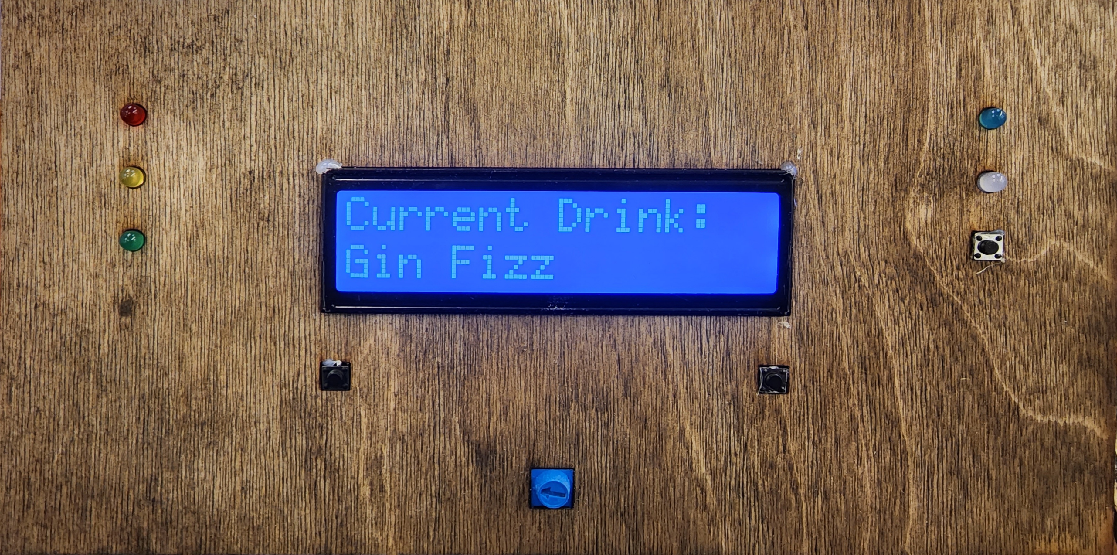 Figure 3: UI when user chooses drink 3, in this case, “Gin Fizz”
When entering the state, the arduino will read the value from the potentiometer which comes as a value from 0 to 1028. In order to get the drink choice number, we will divide the integers. Since drink_choice is an integer, the operation is essentially a floor division. We will also set the LCD screen at this time.
void selecting(){
  // Read the analog once, and blink the LED mapping to the choice.
  // Give user 10 seconds to confirm selection.
  // if confirm -> DISPENSING, else -> READY.
  uint32_t t;
  // initialize selecting state
  if (state != prior_state){
    prior_state = state;
    choice_raw = analogRead(POTSELECT);
    drink_choice = choice_raw/((1028/num_of_drinks) + 1);
    lcd.setCursor(0,0);
    lcd.print("Current Drink:");
    lcd.setCursor(0,1);
    lcd.print(drink_list[drink_choice]);
    sel_time = millis();
    sel_count = 0;
    digitalWrite(RED, LOW);
  }
The following logic simply blinks the LEDs and tracks the amount of times the LEDs blink.
  // Blink LEDs representing choice
  t = millis();
  if(t >= sel_time + BLINK_INT){
      digitalWrite(RED, !digitalRead(RED));
      digitalWrite(YELLOW, !digitalRead(YELLOW));
      digitalWrite(GREEN, !digitalRead(GREEN));
    sel_time = t;
    sel_count++;
  }
There are three possible state transitions from the selecting state. In order to move on to the dispensing state, the user must press confirm before the LEDs turn on and off 10 times. There are three ways to get back to the idle state: The LEDs blink 10 times, the drink choice stays at 0, and the reset button is pressed.
  // Check for state transition
  if (digitalRead(CONFIRM) == HIGH){
    while(digitalRead(CONFIRM) == HIGH) {}
    state = DISPENSING;
    pump1.moveTo(1000000);
    pump2.moveTo(1000000);
    pump3.moveTo(1000000);
    pump4.moveTo(1000000);
  } else if(sel_count == 20 || drink_choice == 0){
    state = READY;
  } else if(digitalRead(RESET) == HIGH){
    while(digitalRead(RESET) == HIGH){}
    state = READY;
  }
The following block prepares the system to switch out of the selecting state.
  //reset LEDs to switch out of selecting state
  if(state != prior_state){
    digitalWrite(RED, LOW);
    digitalWrite(YELLOW, LOW);
    digitalWrite(GREEN, LOW);
    lcd.clear();
  }
}
Dispensing
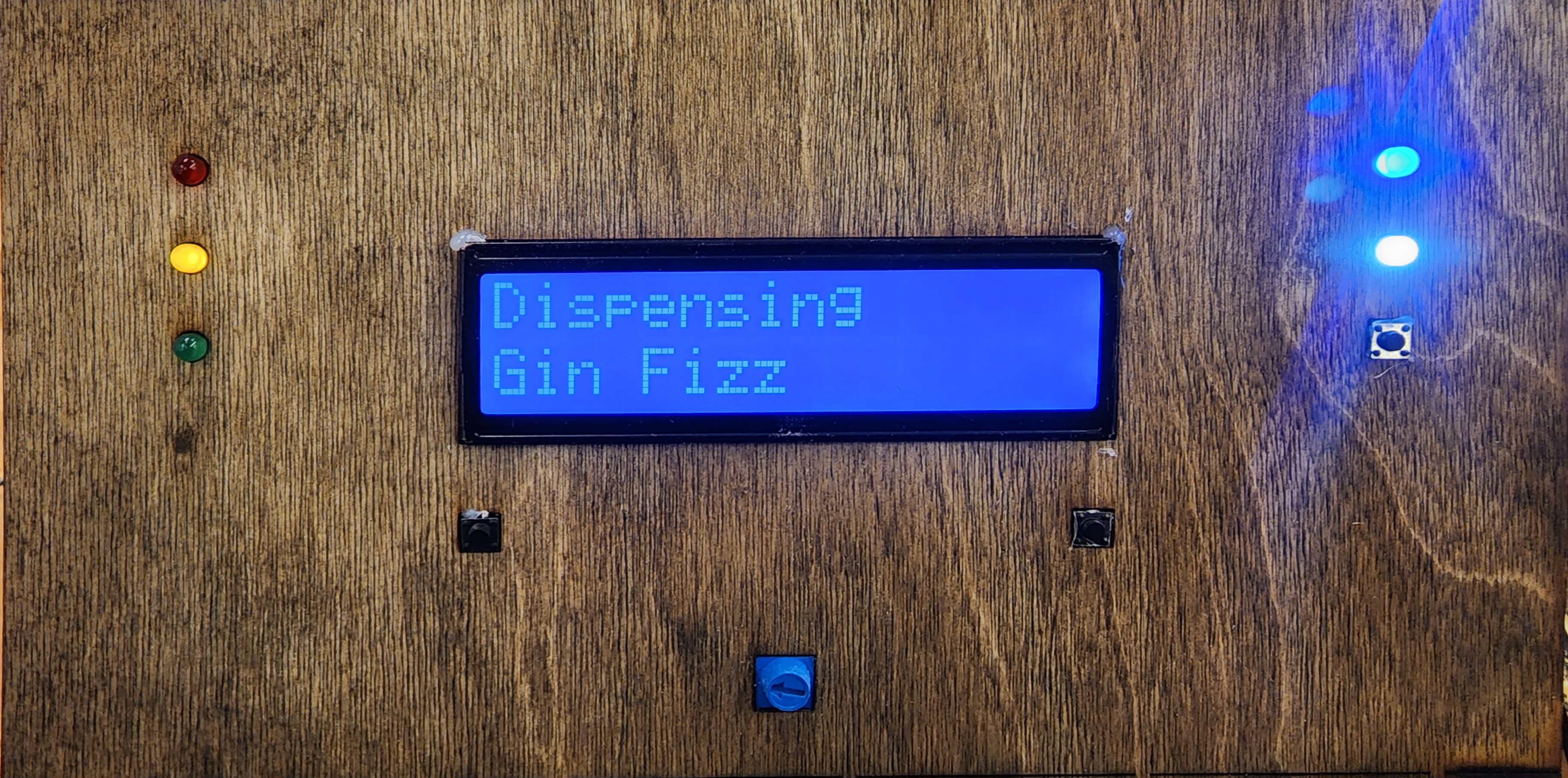 Figure 4: UI while system dispenses drink 3.
When entering the dispensing state, we update the relevant UI. Since the dispensing state actually uses the motors, we turn on the motor drivers and assign the pump durations based on the drink chosen. This came after Sprint 3 once we had a chance to analyze the code more carefully.
void dispensing(){
  // What to do while dispensing
  uint32_t t;

  // initialize dispensing state
  if(state != prior_state){
    prior_state = state;
    digitalWrite(YELLOW, HIGH);
    lcd.setCursor(0,0);
    lcd.print("Dispensing");
    lcd.setCursor(0,1);
    lcd.print(drink_list[drink_choice]);
    dispense_time = millis();
    digitalWrite(ena1, LOW);
    digitalWrite(ena2, LOW);
    for(int pd = 0; pd < num_of_motors; pd++){
      pump_durs[pd] = drink_array[drink_choice][pd];
    }
  }
The refactored form of the code does essentially what the previous revisions did, but condenses into a signle block instead of a bunch of other roughly equally densed blocked. The advantage here is that we set these variables when initiating the state, and get reassigned per drink choice.
  // REFACTORED CODE
  t = millis();
  if(t > (dispense_time + pump_durs[0] - decel_time)){
    pump1.stop();
  }
  if(t > (dispense_time + pump_durs[1] - decel_time)){
    pump2.stop();
  }
  if(t > (dispense_time + pump_durs[2] - decel_time)){
    pump3.stop();
  }
  if(t > (dispense_time + pump_durs[3] - decel_time)){
    pump4.stop();
  }
  if(t > dispense_time + pump_durs[0] && t > dispense_time + pump_durs[1] && t > dispense_time + pump_durs[2] && t > dispense_time + pump_durs[3]){
    state = DONE;
  }

  pump1.run();
  pump2.run();
  pump3.run();
  pump4.run();
To leave the state, we must ensure that the motors get shut off. We take advantage of this by running .stop() which sets the target 0. To make sure that the motors had been fully reset, we run setCurrentPosition(0) to make the stepper motors think that they’ve not gone anywhere.
  //if RESET button is hit, will abort action and return to READY
  if(digitalRead(RESET) == HIGH){
    while(digitalRead(RESET) == HIGH){}
    pump1.stop();
    pump2.stop();
    pump3.stop();
    pump4.stop();
    state = READY;
  }

  // Turns off motors to move on to the next state
  if(state != prior_state){
    digitalWrite(ena1, HIGH);
    digitalWrite(ena2, HIGH);
    digitalWrite(YELLOW, LOW);
    pump1.setCurrentPosition(0);
    pump2.setCurrentPosition(0);
    pump3.setCurrentPosition(0);
    pump4.setCurrentPosition(0);
    lcd.clear();
  }
}
Done
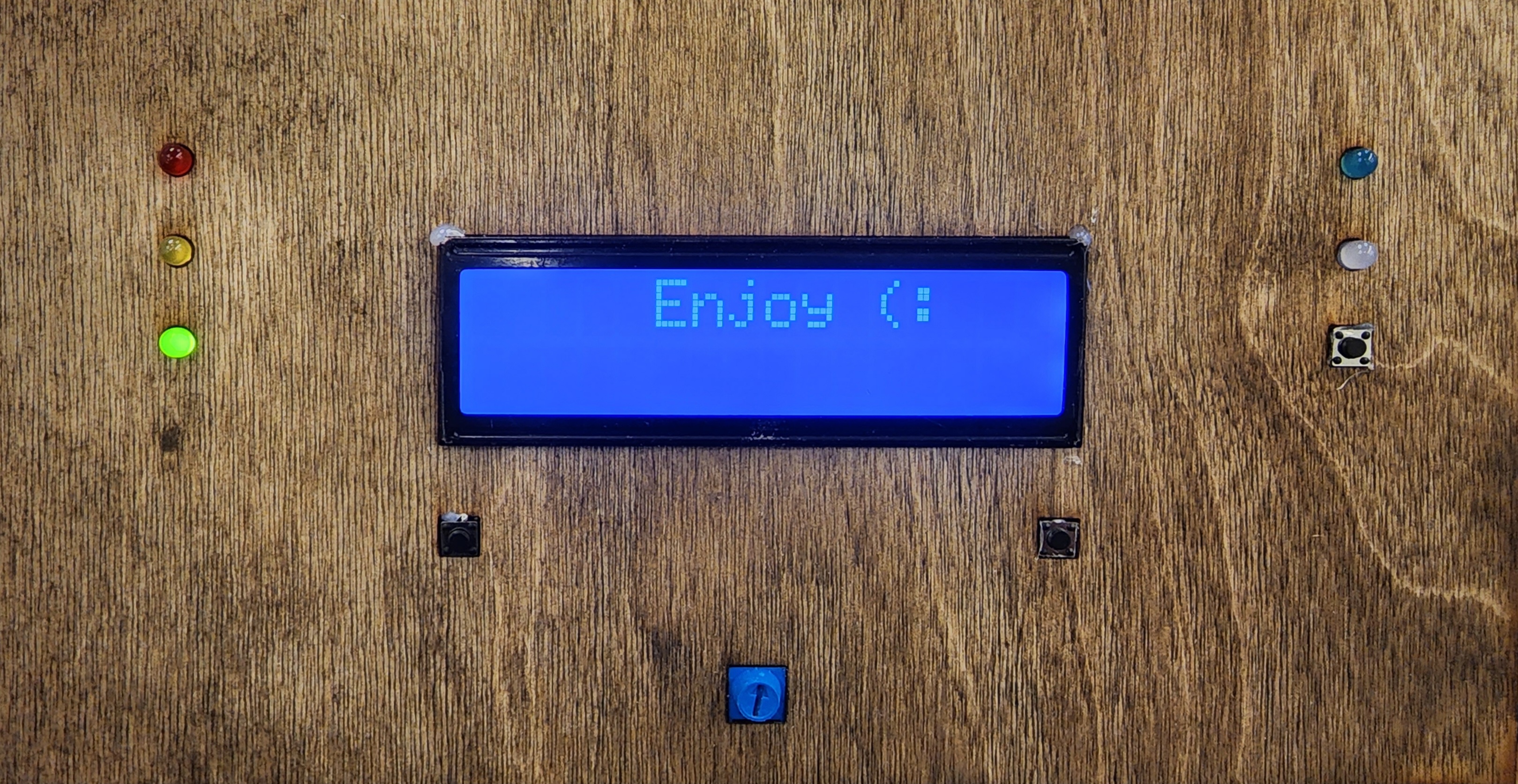 Figure 5: UI when system has finished dispensing.
The main purpose of the done stage is to make sure that we are getting out of the dispensing correctly. It also gives us some time to prompt the user to take their drink. This stage will automatically go to the idle stage after 5 seconds
void done(){
  // What to do when the barbot has finished.
  if(state != prior_state){
    prior_state = state;
    lcd.setCursor(5,0);
    lcd.print("Enjoy (:");
    digitalWrite(GREEN, HIGH);
  }
  delay(5000);
  digitalWrite(GREEN, LOW);
  lcd.clear();
  state = READY;
}
Maintainance Mode
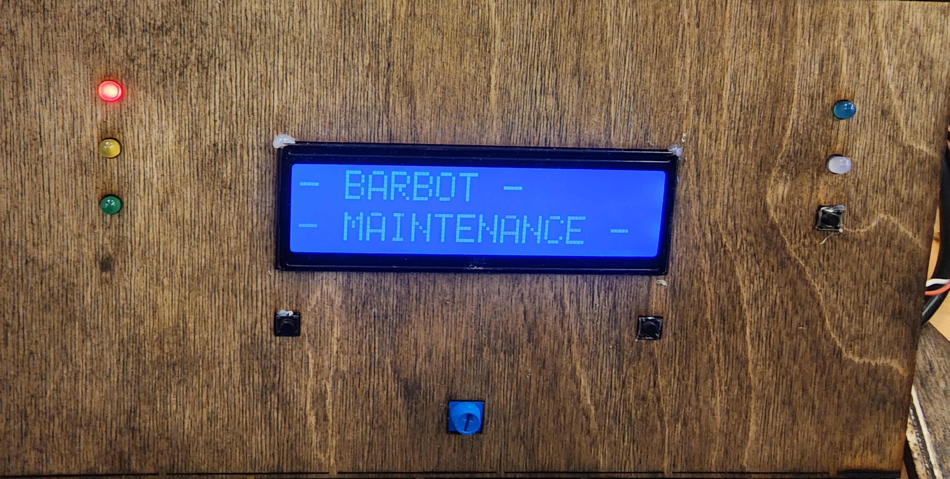 Figure 6: Display as the system transitions from user mode to maintainance mode.
In order to enter the Maintainence mode, the user must hit the reset button while the barbot is in its idle mode. The purpose of the maintainace mode is to allow a Barbot owner to both set the liquids to the tip of the pump, and to run clean operations whenever changing out the liquids. For the purpose of the code, our idle state in maintainance mode is “disabled”, as in ‘not enabled’, as in, waiting for an instruction.
case SETUP:
      switch(curr_state){
        case DISABLED:
        disabled();
        break;
        case CLEAN:
        clean();
        break;
        case SET:
        set();
        break;
      }
    break;
Idle
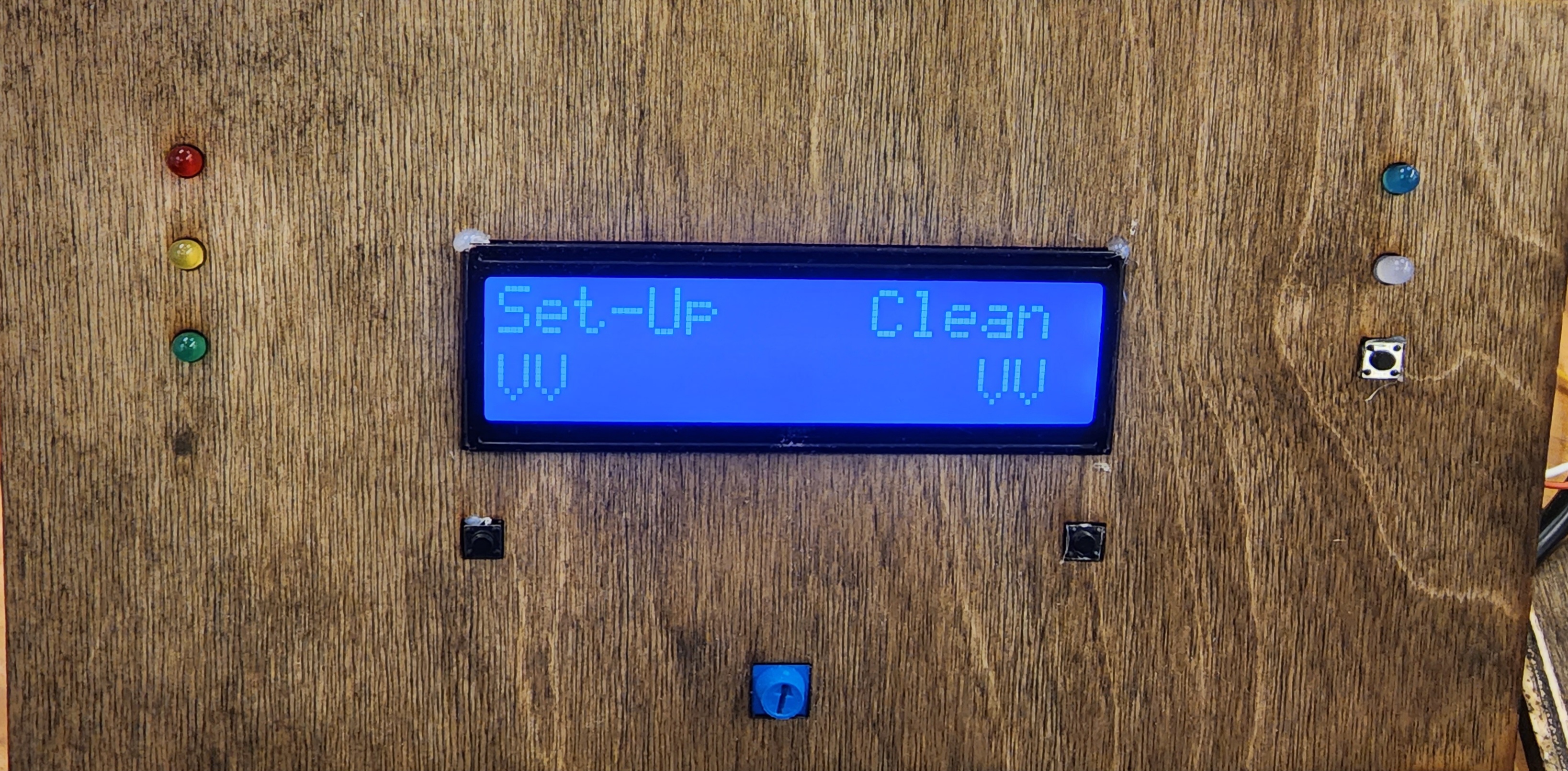 Figure 7: Display while the system is in the maintainance idle state.
The idle state in maintainance mode initializes its state by displaying its transition, and then setting the screen with the two options: Set-Up and Clean.
void disabled(){
  // Menu mode for maintenance
  uint32_t t;
  // Initialization mode
  if (curr_state != prev_state){
    prev_state = curr_state;
    digitalWrite(ena1, HIGH);
    digitalWrite(ena2, HIGH);
    lcd.clear();
    digitalWrite(WHITE, HIGH);
    dis_time = millis();
    dis_count = 0;
    lcd.setCursor(0,0);
    lcd.print("- BARBOT -");
    lcd.setCursor(0,1);
    lcd.print("- MAINTENANCE -");
    lcd.setCursor(0,2);
    lcd.print("- MODE -");
    delay(1000);
    lcd.setCursor(0,0);
    lcd.print("Set-Up    Clean");
    lcd.setCursor(0,1);
    lcd.print("VV           VV");
  }
The following block of code actually looks out for the button presses. Once the buttons have been pressed, we set the steps to move arbitrarily high again, since we are controlling accuracy through time. Note, we are also looking out for another reset press which would take the system back to the user mode.
  // Allow switch to maintenance options
  if (digitalRead(CONFIRM) == HIGH){
    while(digitalRead(CONFIRM) == HIGH) {}
    pump1.moveTo(1000000);
    pump2.moveTo(1000000);
    pump3.moveTo(1000000);
    pump4.moveTo(1000000);
    curr_state = CLEAN;
  }
  if(digitalRead(SELECT) == HIGH){
    while(digitalRead(SELECT) == HIGH){}
    pump1.moveTo(1000000);
    pump2.moveTo(1000000);
    pump3.moveTo(1000000);
    pump4.moveTo(1000000);
    curr_state = SET;
  }
  if(digitalRead(RESET) == HIGH){
    while(digitalRead(RESET) == HIGH) {}
    mode = USER;
    pump1.setCurrentPosition(0);
    pump2.setCurrentPosition(0);
    pump3.setCurrentPosition(0);
    pump4.setCurrentPosition(0);
    lcd.clear();
    lcd.setCursor(4,0);
    lcd.print("Ready...");
    digitalWrite(WHITE, LOW);
  }
}
Set Up
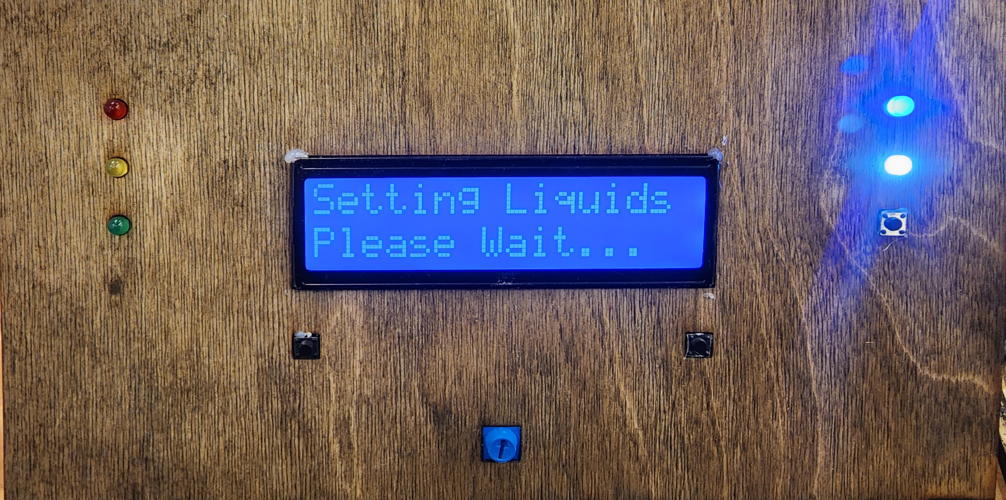 Figure 8: UI while the system is setting the liquids to the tip of the nozzle.
Setting Up the liquids entails running the motors for just long enough such that the liquids will go from the bottom of the tubing to right at the tip. After running tests on our system, we figured out that 9 seconds was the amount of time it took the liquid to reach the tip of the nozzle. We set this parameter when defining our variabled. The rest of the code is essentially the same as the dispensing code, except that all of the motors are controlled by a single time parameter instead of individual times. Note that the set up time will depend on the acceleration rate and the length of the tubing. Though we cannot provide equations relating these numbers, we acknowledge that both are factors in how quickly liquid will go from point the bottom of the tubing to the opposite tip.
void set(){
  // Liquid Setting Mode
  uint32_t t;
  // Initialize
  if (curr_state != prev_state){
    prev_state = curr_state;
    digitalWrite(ena1, LOW);
    digitalWrite(ena2, LOW);
    lcd.clear();
    lcd.setCursor(0,0);
    lcd.print("Setting Liquids");
    lcd.setCursor(0,1);
    lcd.print("Please Wait...");
    setup_time = millis();
  }

  t = millis();
  if(t < setupdur + setup_time){
    digitalWrite(BLUE, HIGH);
    digitalWrite(WHITE, HIGH);
  }
  if(t > setupdur + setup_time - decel_time){
    pump1.stop();
    pump2.stop();
    pump3.stop();
    pump4.stop();
  }

  pump1.run();
  pump2.run();
  pump3.run();
  pump4.run();

  // Stop motors and switch stage after set amount of time.
  t = millis();
  if (t > setupdur + setup_time){
    curr_state = DISABLED;
    pump1.setCurrentPosition(0);
    pump2.setCurrentPosition(0);
    pump3.setCurrentPosition(0);
    pump4.setCurrentPosition(0);
  }

  // delete later
  if(digitalRead(RESET) == HIGH){
    while(digitalRead(RESET) == HIGH){}
    pump1.stop();
    pump2.stop();
    pump3.stop();
    pump4.stop();
    pump1.setCurrentPosition(0);
    pump2.setCurrentPosition(0);
    pump3.setCurrentPosition(0);
    pump4.setCurrentPosition(0);
    digitalWrite(BLUE, LOW);
    digitalWrite(WHITE, LOW);
    curr_state = DISABLED;
  }
}
Clean
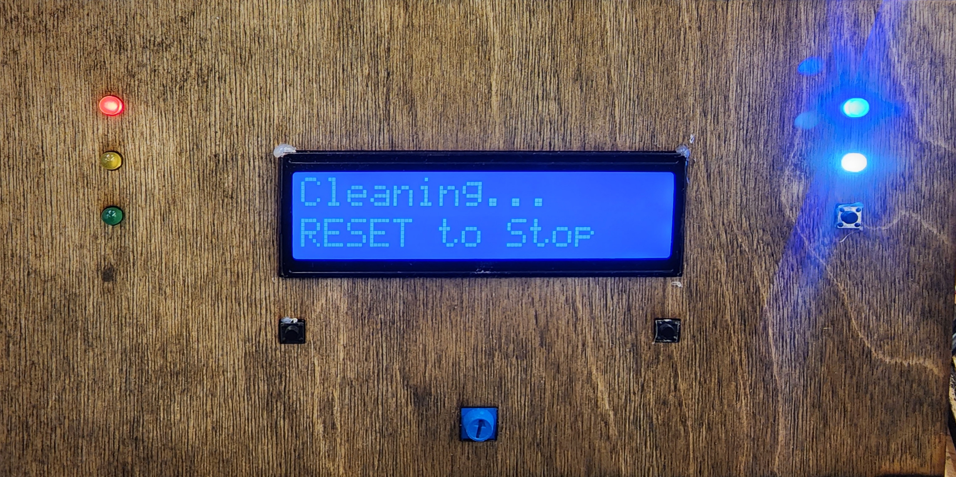 Figure 9: UI while the system runs its cleaning cycle.
It would be far too redundant to paste the code for this state, since it is identical to the setup block, except that instead of setupdur and setup_time, we would be using cleandur and clean_time. This is because they serve the exact same function, but for a different amount of time. In hindsight, we could have attempted to create a function encapsulating the “run all of the motors at once” functionality with the _dur and _time variables serving as the function arguments. Since they both have the same transition, we could even have a selecting and dispensing stage. This may or may not serve as more efficient code; however, this implementation has given us no issues to date.
Source Code:
| Electrical | Mechanical |