Mechanical Subsytem
The main mechanical developments achieved were the pumps and the casing.
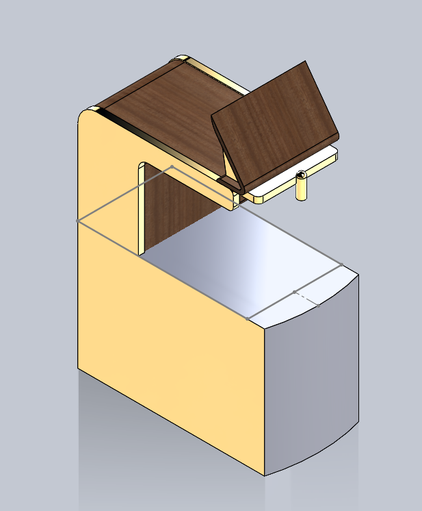
Casing

Figure 1: CAD of the Barbot
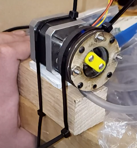
Pump Assembly

Figure 1: Image of the redesigned pump.
Our final pump design we used a combination of M3 and 6-32 screws to secure the pump assembly to the motor. It is constructed of ⅛ and ¼ in mdf and hardboard respectively for the outer shell. For the central hub it consists of a 3D printed spacer, 4 1454 bearings and a coupler to engage the motor shaft. This arrangement allows for a peristaltic effect to be placed on the 1/4in OD tubing within the pump assembly. For additional stability some amount of silicone scrap was placed under the motor and the whole assembly is ziptied to some scrap wood to facilitate integration and stability.
| Firmware | Electrical |