For this project, the Mechanical Team focused on creating the housing for the bottles and dispensing mechanism.
To download any of our CAD files, go to this GrabCAD folder.
Creating the Dispensing Mechanism
Solenoid Valves
One of the most important parts of the mechanical system was finding the most efficient and inexpensive pumps to use.
Over the course of this project, the team put much thought into the best way to transport water/fluid from our 2L bottles to the cup. At the start of the project, we thought that solenoid valves were the best option, especially since they could be controlled easily through the Arduino. However, after purchasing and testing the valves, we found that the flow rate was much too slow for our purposes. Additionally, due to the pressure requirement of solenoids, we were worried that the liquid would stop flowing once the volume decreased to a certain amount. Overall, we decided to pivot to using peristaltic pumps after taking the following into consideration: the flow rate; the orientation of the solenoids on the bottles; and the ease of integration with the overall system.
Peristaltic Pumps
After much time searching for alternatives, we found that peristaltic pumps would be the easiest to integrate with the rest of the mechanical and electrical setup we had. Peristaltic pumps hold liquid by pinching the tube and dispense liquid by releasing pressure on the tube. Our pumps require 12V, so we were able to buy a 12V power supply to share between our four peristaltic pumps. Ultimately, we decided that the peristaltic pumps were a much better option, as they proved to be less expensive, have a great non-pressurized flow rate, and were very easy to integrate.
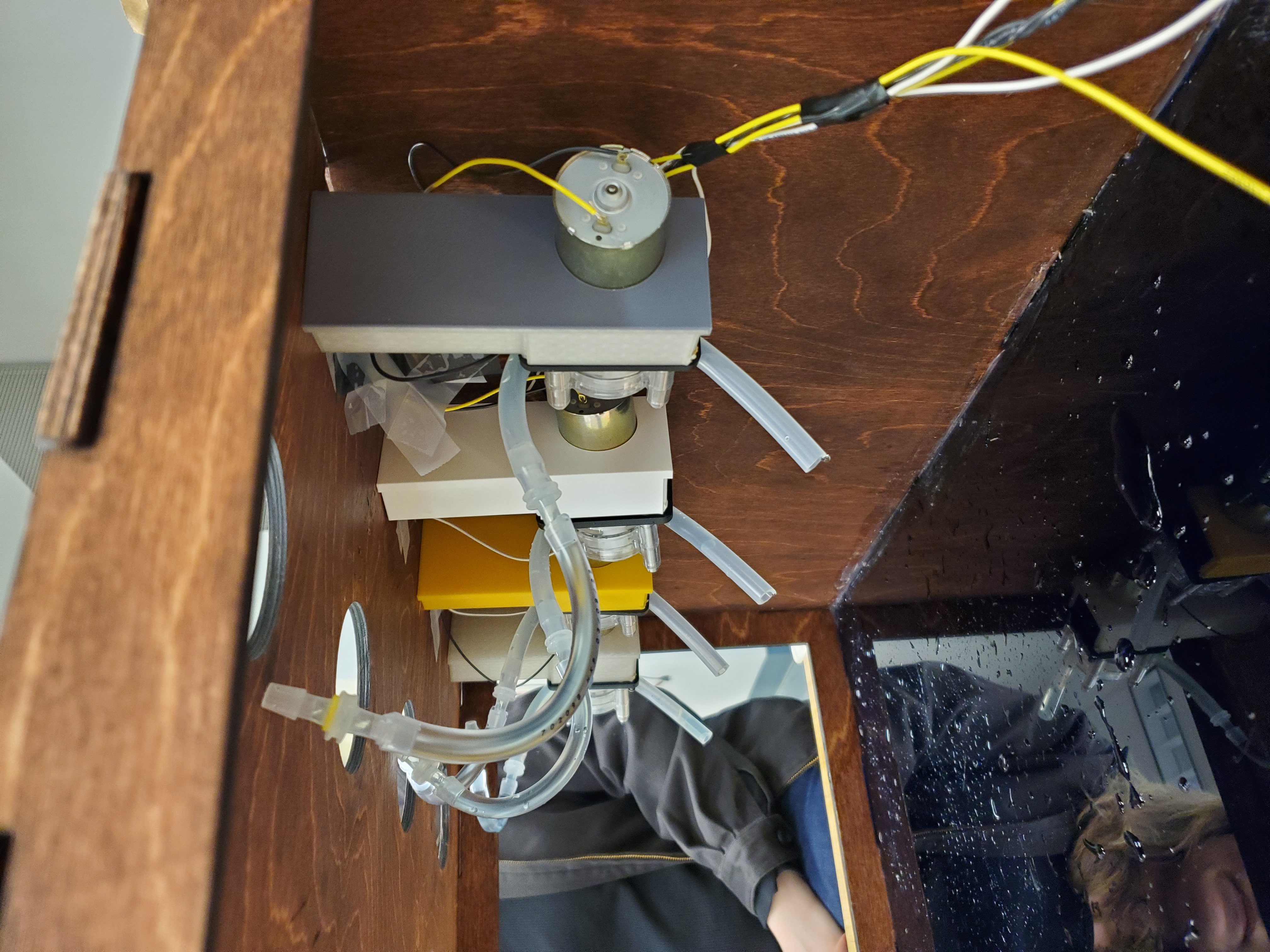
Our peristaltic pump setup
CAD Pieces
Housing
To contain the dispensing mechanism and bottles, we created a CAD of our housing. The housing was designed in OnShape and was laser cut using quarter inch materials. It was built to accommodate four bottles on top with a clearance of 12 inches underneath and 24 inches across. For our first iteration of the housing, we used all acrylic walls. While this was functional we found that the acrylic scratched easily and showed glue spots from where it was combined at the joints. For our final iteration, we transitioned to a wood and acrylic hybrid. The wood was stained and treated with a water resistant finish and we chose to add a small design onto the back with our names for personalization. We opted for wood on the top, side, and back panels since these areas were not at risk of getting repeatedly wet. Additionally, we included the front wall as clear acrylic so that users could see their drink being made. We ended up removing this front piece, since we didn't manage to fully achieve our stretch goal of a conveyor belt, and keeping the acrylic made it more difficult to move the cup around. The floor piece was acrylic to make clean up easy in the case of any spillage.
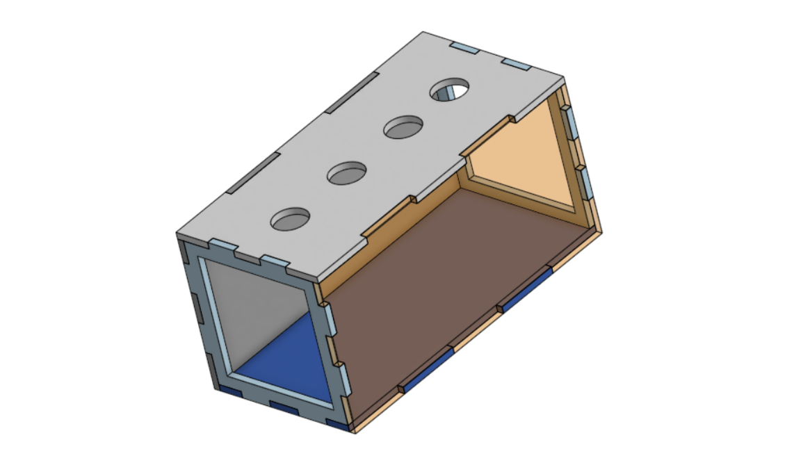
CAD of our housing
Spouts
The spouts were created to accommodate the 2L bottle cap size with the addition of threading on the inside to help secure it. The end of the spout nozzle was built to accommodate the adaptor piece of the tubing coming from the peristaltic pumps. We later modified this design later, making it thicker, as the original version tended to leak. They were 3D printed using PLA filament.
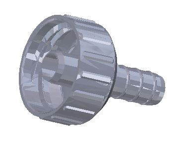
CAD of our 3D printed spouts
Peristaltic Pump Mounts
In order to hold the dispensing mechanism in place, we needed a way to secure the peristaltic pumps. The pump mounts are perfectly fitted and are screwed into place with the help of heat-set inserts. Thanks to the lightweight pumps only requiring a single screw to secure the mounts, these allowed for a modular design. It was very easy to move things around as necessary, and made mounting the four pumps very simple. There is also the ability to screw into three more surfaces of the pump for additional stability and movement control. The design of the mount also makes it much easier to disassemble in order to clean or change pumps.
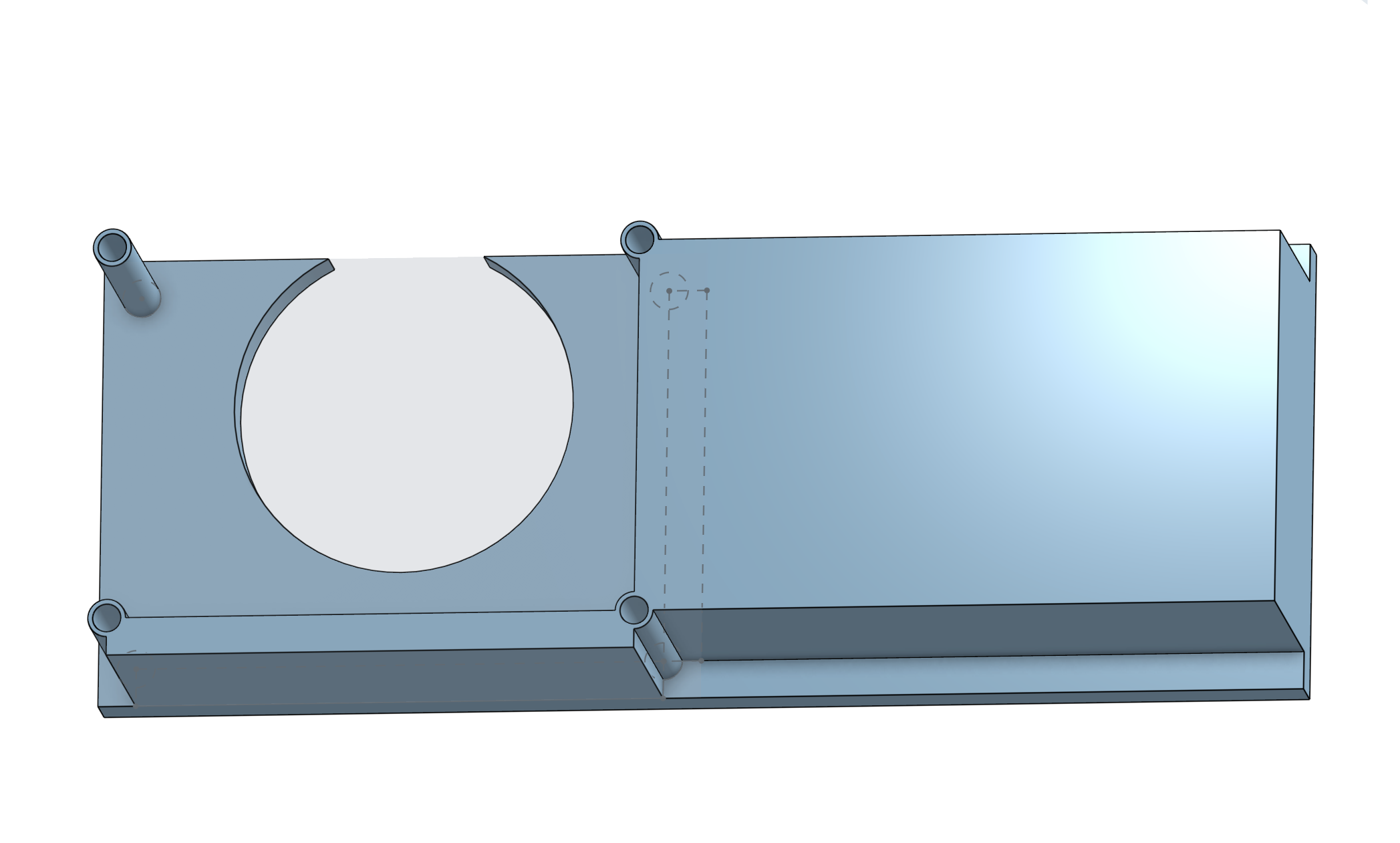
CAD of our peristaltic pump holders
Stretch Goal Attempt - Rail Integration
For our stretch goal, we chose to aim to integrate a functioning x-axis conveyor belt style system. To do this, we purchased a Nema 17 Stepper Motor, accommodating Stepper Motor Timing Belt, 2020 Aluminum rail, and a gantry plate. First to allow the rail system to be self-contained, the stepper motor and tensioner on the opposing sides to each other needed to be directly connected to the 2020 aluminum. To achieve this, we created the stepper motor mount and tensioner to be screwed in and held by a bolt and nut inside the side slot of the 2020 aluminum. Once we had a way to hold the stepper motor onto the rail and a way for the belt to turn on the other side we then ran the timing belt around the rail and connected it to the gantry plate. To then secure our self contained conveyor belt system to the housing, we created mounts that slide onto the right and left side of the 2020 aluminum and have two legs underneath that fit between the quarter inch housing material on the sides.
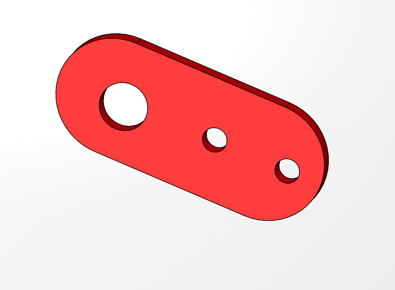
The CAD of the V-slot tensioner for the proposed conveyor belt
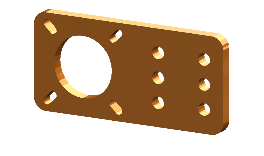
The CAD of our mount for the stepper motor
Unfortunately, the software team didn't have enough bandwidth to get the conveyor belt and stepper motor system working on time, so we were not able to integrate this piece into our project. However, it was a great learning opportunity and had we had more time, we could've got it working. If the stepper motor integration were to have been completed, we would've screwed the rail legs into the housing as necessary.
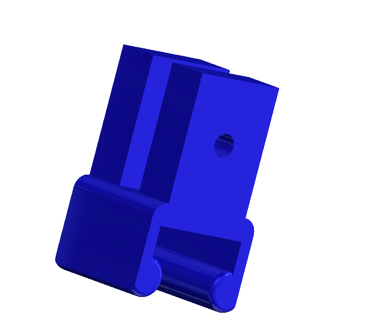
The CAD for holding the linear rail in place