The software team focused on creating the graphical user interface (GUI) and the Arduino code to control the pumps.
For both the Python GUI code and Arduino valve control code, go to this Github folder.
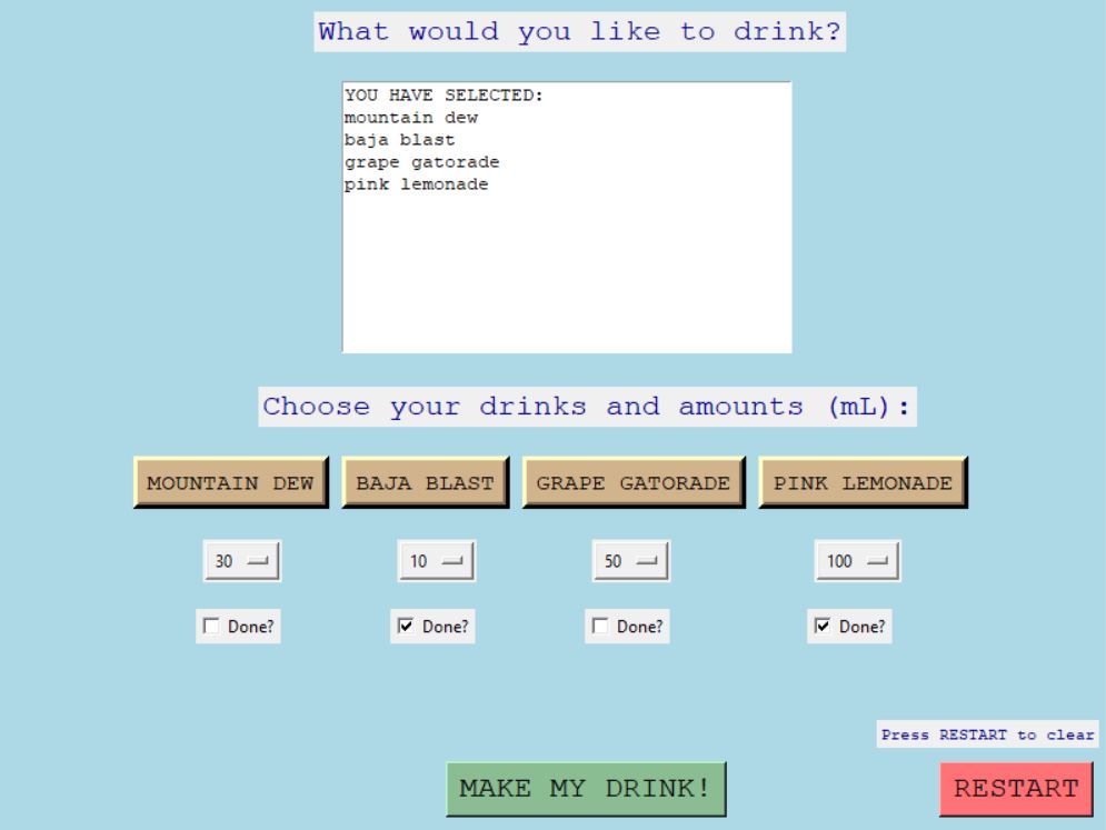
Our GUI, ran from a Python script
Creating the User Interface
Liquid Crystal Display (LCD)
The software portion of this project consisted largely of creating the graphical user interface.
From the start, the group knew that we wanted to utilize a user interface (UI) from which the user could decide what drinks and how much to pour. Since our software team wanted to learn how to work with Raspberry Pi during this project, we initially decided to display the UI on a 4.5 inch LCD, which was plugged into the Raspberry Pi. In this manner, the GUI could be coded in Python using the Raspberry Pi and displayed compactly. However, our software team ran into issues with troubleshooting and getting the LCD to work as intended. For the sake of time and sanity, we decided to switch over to displaying the GUI using a laptop.
Python's Tkinter Library
To create the GUI, we used Python's Tkinter library. This library makes building a GUI much simpler and includes helpful methods for displaying and coding the effect of buttons, dropdown menus, and much more. With the help of Tkinter, we were able to create a GUI that could be run from the laptop's terminal. This GUI provides the user with the ability to choose from four drinks and to choose how much of each drink to be dispensed. It also includes a RESTART button and textbox that displays what has been selected so far.
Since our software team felt that controlling the peristaltic pumps through the Arduino IDE would be simpler, they decided to send the information—the pump and amount to dispense—to the Serial port from the GUI. The Arduino could then read from the Serial port and extract the desired information.
Controlling the Pumps with Arduino
The Arduino directly controlled the four peristaltic pumps by sending low or high power to the respective PWM digital pin. The code split up the information received from the Serial port into a more manageable manner and made note of which information corresponded to the pump number and the amount to dispense.
Inside of the Arduino code, there were calculations to determine the length of time to open the valve for. In prior tests, we measured the flow rate of the pumps and accounted for that in our calibration equation. Once the Arduino separated the data, it opens one pump after another.
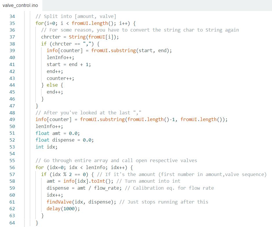
Snippet of Arduino code that reads the data from the Serial port and separates it into groups.