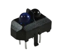
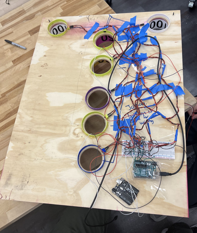
To identify when the ball enters the scoring hole, we implemented Sharp IR reflective sensors. These sensors are designed with an operational range spanning from 2 - 15 millimeters, ensuring precise detection of the ball's entry into the hole. Each sensor consists of an infrared emitter and a phototransistor, which is directly influenced by the presence of light or an object approaching closely. The voltage decreases when an object enters its range, allowing us to accurately detect the ball in the hole.
The ball launcher is powered by two 12V motors, capable of reaching a maximum speed of 1000 RPM. Each motor is connected to a 2-inch compliant wheel. To regulate the speed of the wheels effectively, we integrated an L298N motor controller board, which offers precise control over the motor speeds and provides a range of options for adjustments. The motors are activated when a certain boolean in the code is changed when a ball is detected by one of the sensors. The motors run for a designated amount of time and then shut off. A secondary function of the motors is to keep the balls in the system. If the wheels are not running that acts as a wall.
In order to wire up all of our sensors and motors into one place to communicate with the Arduino and motor controller, we connected them to a breadboard. We color coded the wires following standard Vcc and GND and labeled the ends to differentiate between the phototransistor and infrared emitter. We also twisted them to avoid any wires coming into contact with each other.
For lighting, we have multiple WS2812b 60/m addressable RGB strips. These are driven off the Arduino, but like motors have a high power requirement. Due to that, they have their own 5v power supply. There are three zones, one on the ramp, another on the board, and a third along the top rim of the main structure. They are driven by an example library called Fire2012 provided by FastLED. FastLED provides excellent tools for driving addressable RBS strips, and we utilized this to be able to create a cool lighting display.
The biggest challenge we encountered during this process was that our sensors did not work. Our original circuit design had us threading all the sensor wires through a hole in the backboard, meaning our breadboard was on the exterior of the game. Doing this caused the sensors to not work as expected. We would take off the main board with all the holes, test the sensors, and they would work perfectly. However, as soon as we put the board back onto the rest of the system and threaded the wires through, we would not get the expected sensor readings, or we would not get readings at all. Once we realized this, we decided to mount the breadboard on the interior of the board, right under the main scoreboard. This fixed our issue of sensor readings, and it reduced the risk of us accidentally disconnecting the wires from the sensor by pulling on them too hard.
created with
HTML Website Builder .