Circuit Diagram
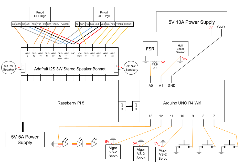
We used Google Drawing to create our circuit diagram. It contains all of the following:
- Raspberry Pi 5
- Arduino Uno R4 Wifi
- Adafruit I2S 3W Stereo Speaker Bonnet
- 8W 3Ohm Speakers (2)
- PmodOLEDrgb Screens (3)
- Vigor VS-2 Servo (3)
- REXTiN WS2811 Pixel LEDs (3)
- Force Resitive Sensor
- Hall Effect Sensor
- Push Button (3)
- 5V 10A Power Supply
- 5V 5A Power Supply (Raspberry Pi)
The Raspberry Pi is the main controller of the system, handling high-level tasks such as audio and screens, and coordinating with the Arduino through serial. It manages the state machine while providing variables to the Arduino for low-level control. The Arduino manages real-time interactions with sensors and servos, ensuring responsive behavior. The raspberry pi is powered by a dedicated 5V 5A power supply, and the Arduino, speaker bonnet, speakers, and OLED screens draw power through the Raspberry Pi. All other components are powered by an additional 5V 10A power supply. The various components are interconnected to facilitate communication and control, enabling the creature to perform its intended functions.
Individual Components
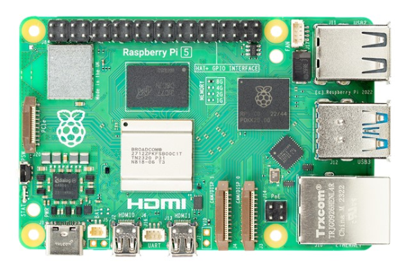
The Raspberry Pi 5 acts as the brain of the creature. It manages emotional state, plays audio through the speaker bonnet, and displays visuals on the OLED screens. It stores and runs all the necessary Python code for the creature to function, while also storing, compiling, and uploading code to the Arduino.
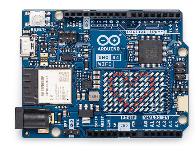
The Arduino Uno R4 Wifi acts as the heart of the creature. It runs one continuous script that takes in sensor data from the force resistive sensor, hall effect sensor, and push buttons to allow the creature to respond to user interactions in real time. It also controls the servos and pixel LEDs to bring movement and convey information about the creature's emotional state.
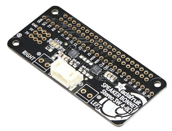
The speaker Bonnet connects directly to the entire Raspberry Pi pinout, and uses GPIO 18, 19, and 21 to play audio files stored on the Raspberry Pi through speakers. It uses the I2S protocol to communicate with the Raspberry Pi. It also has breakout holes that allow for other components, namely the screens, to be soldered directly onto it for a stable connection. It is one of the highest power drawing components connected to the Raspberry Pi, requiring up to 3W per channel at max volume.

There are two speakers attached directly to the speaker bonnet. They are not particularly loud, or the best quality. This was a tradeoff we made in order to stay within our power budget, as we have a lot of peripherals connected to the Raspberry Pi and Arduino that also draw a lot of power. We also wanted them to be small enough to fit within the creature's base. Additionally, we wanted to imitate the slightly eerie sound of a furby, and the lower quality speakers help with that effect.
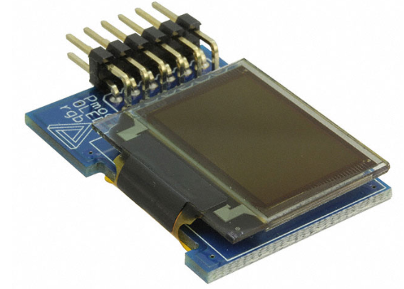
The 2 OLED screens act as the creature's eyes. They display different animations depending on the creature's mood. The screens are connected directly to the speaker bonnet via soldered connections, using SPI communication. They are powered through the Raspberry Pi's 3.3V and GND pins and each take 6 GPIO pins along with COPI and Serial Clock. They are the part of the system that had to be most carefully wired due to the large number of wires and need to travel up into the moving creature.

There are 3 servos inside of the creature's base. These act as spine control. They are each attached to a spool that has string around it, and spinning the servos pulls on the string to pull the creature's spine toward that corner. This allows the creature to lean and wiggle and move in different directions, conveying emotion.
The Pixel LEDs are individually addressable. Their data line is wired to the Arduino, while their power and ground are connected to the 5V 10A power supply. They are on the front panel of the creature's base. 2 of them act as mood indicator lights, while the third acts as a back status light.
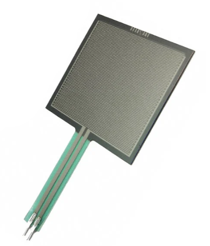
The force resistive sensor is placed on top of the creature's head. This senses any weight on top of the creature. It's intended to allow users to push on the head. It was calibrated to detect anything from a light brush to a firm press. There was an additional resistor wired to it to allow for increased sensitivity to lighter touches.
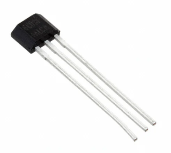
The hall effect sensor is embedded in the beak of the creature. Its intended purpose is to detect when an object with an embedded magnet is placed into the beak. It is calibrated to detect a magnet within about 2mm. This allows users to "feed" the creature.

There are 3 buttons in the base of the creature, one is assigned to each light. One acts as a "feed" mode button so that the creature's hall effect sensor is activated to detech the food, one acts as a "play" mode so that the creature's force sensor is activated to detect head petting, and one acts as a back button to interupt states and return to idle. If all three buttons are pressed, Raspberry Pi will run a shutdown script that safely powers down the screens and resets the Arduino.