
Overview
The heart of the mechanical system is a Core-XY gantry, scaled up from the typical size of a standard 3D printer so its end effector can reach the center of every square on the board, including capture and promotion squares. Mounted on the end effector of the gantry is a “third axis” servo with a rack and pinion to translate a magnet up and down, depending on whether the gantry is moving a piece. This end effector system needed to be extremely reliable, avoiding binding, slipping, or any piece dropping over the course of a 30-minute game. The gantry chassis is fully constructed using 1-inch aluminum extrusions and held together with 3D-printed brackets.
Mounted on top of the gantry is the chessboard itself, made from a ⅛ inch thick sheet of chipboard (thin MDF). The board is laser-cut to distinguish each of the 120 squares as well as the white and black squares. We added a black and white border around the entire playing field to visually separate the board from the squares. This piece also served as a reinforcement for the board, keeping it from bowing under the weight of the PCBs, and concealing all the mounting screws.
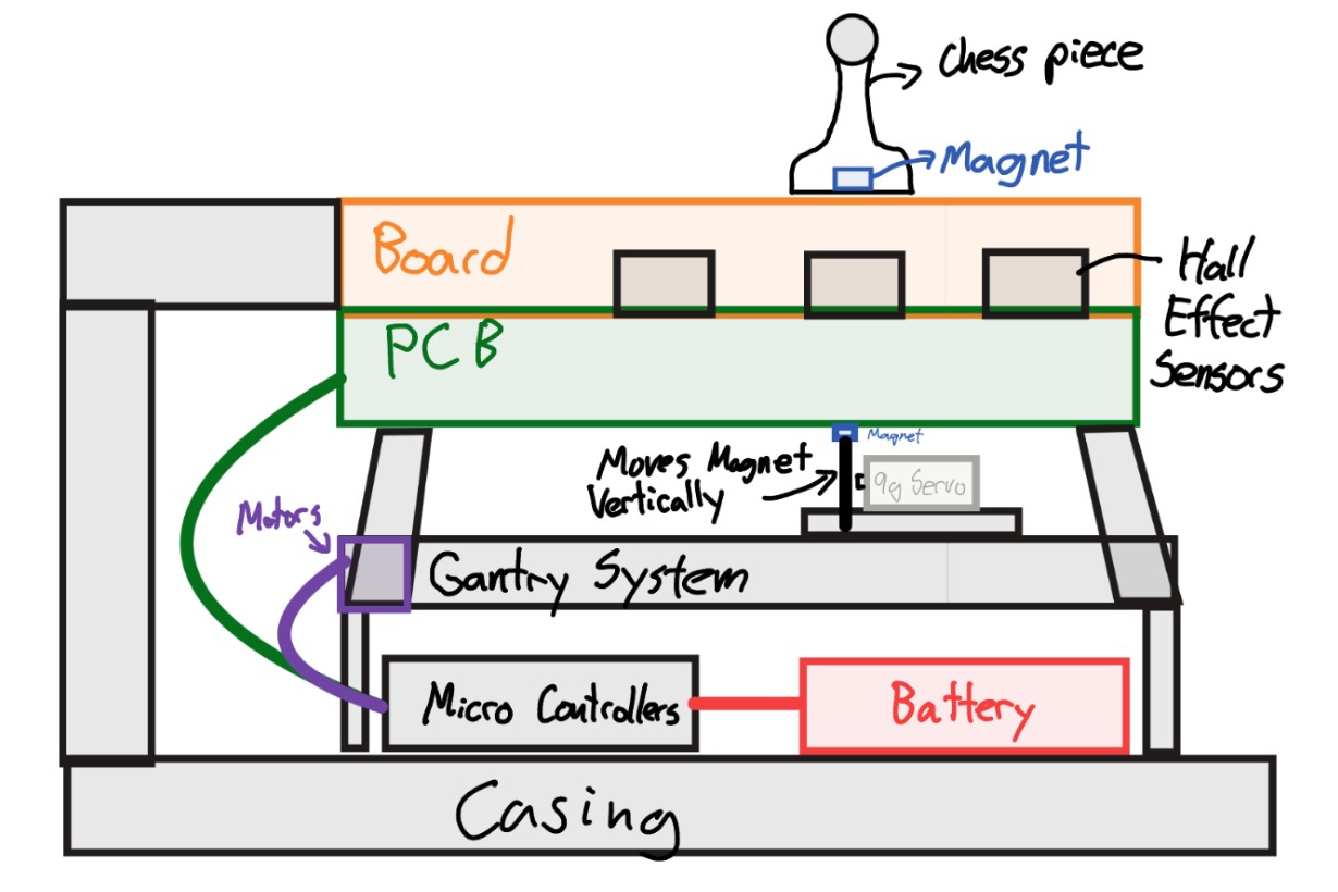
A sketch of how we planned the cross-section of the board to look like.
Key Design Decisions
- Gantry System over a Robot Arm Pick and Place System and Computer Vision or Two-Degree-of-Freedom Linkage System (SCARA Mechanism)
- One of our goals was to keep the entire assembly contained with no visible moving components, emphasizing the “magic” of the automated movement.
- A robot arm and camera would ruin the seamless aesthetic and “all-in-one” nature we were aiming for!
- A linkage system would allow for a more compact design, but it would be an unnecessarily overcomplicated approach for a small team in a tight timeframe, and it may not be very robust.
- CoreXY Gantry over a traditional Cartesian system
- One of our learning goals was to implement Core-XY motion system and learn more about the different methods of gantry movement in general.
- Core-XY allowed us to control the movement of both the X and Y axes with the same two motors, simplifying the overall package.
- This movement system allowed us to mount both motors on the same extrusion, removing the need to mount a motor on top of the X-axis, thereby reducing the overall height of the assembly.
- Due to the length of our X-axis and its tendency to bind up when it isn’t perfectly perpendicular to the Y-axis guide rails, we would have needed 2 stepper motors to translate the X-axis extrusion across the Y rail, with another motor to translate the end effector across the X rail.
- Core-XY is a robust system rigid system used to produce quick, very repeatable movements like in a 3D printer.
- Permanent Magnet End Effector over an Electromagnet
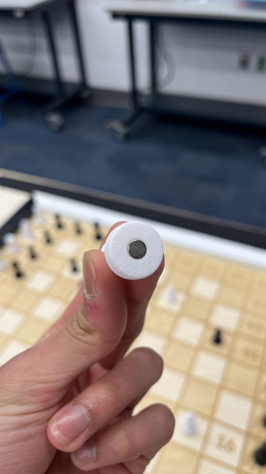
- Through testing, we found that an electromagnet, even unpowered, would still be attracted to the pieces at all times, as it was made out of stainless steel, and our pieces had embedded magnets. Our pieces had to have embedded magnets so that they could be detectable with our hall effect sensors.
- We found that adjusting the distance between a permanent magnet and the pieces was a better option, as the end effector could slide upward, attract, and move the pieces while being able to lower the magnet and make rapid movements.
Gantry
We designed a Core-XY gantry based on a modified version of the Prusa Core One.
Source: 3D Printing Stack Exchange
Technical Details
Type:
- Core-XY
Working Range:
- X: 18 inches
- Y: 22 inches
Motors Used:
- 2x Nema-17 Stepper Motors
Overall Dimensions:
- 35 by 28 inches with Side Panels
- 34 by 25 inches without Side Panels
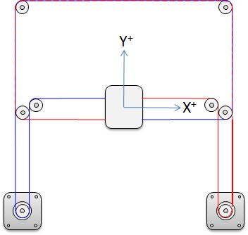
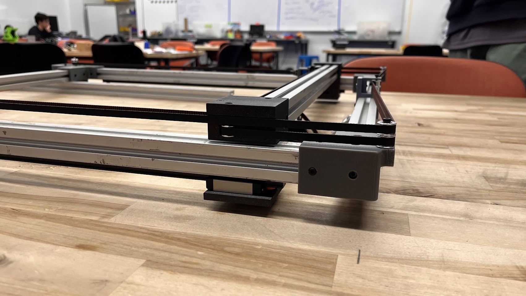
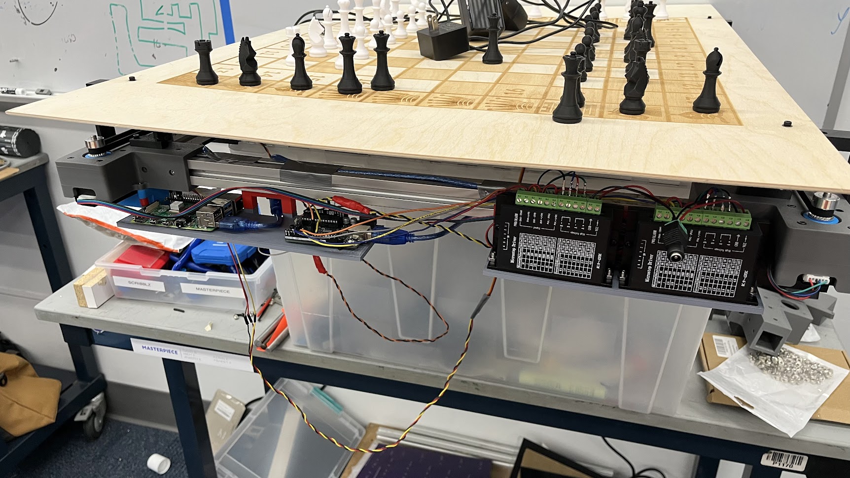
The core of Masterpiece’s motion system is a belt-driven Core-XY gantry mounted beneath the chessboard. Using linear rails, idlers, and belt tensioners, the gantry can position an end effector under any square with repeatable accuracy while avoiding racking or binding. Hard end stops and homing routines prevent over-travel and give us a consistent reference for all motion.
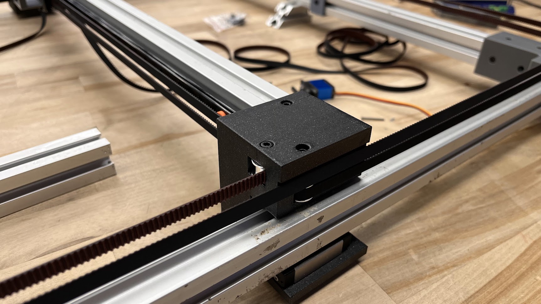
We added our tensioners opposite the motors and stacked our two belt paths to keep the assembly compact. In addition, we attached the Y-axis linear rails to the underside of the Y-axis extrusions, reducing the area between the board and gantry. We chose this configuration rather than attaching the linear rails to the inside face of the extrusions.
The rails span beyond the 8×8 playing area, so the carriage can reach capture zones off to the side of the board. This lets us slide captured pieces completely off the main grid and keeps the motion path clean and collision-free.
Design Process
Starting with a drawing of a standard chessboard, we planned out the overall size of the playing field, taking into account the need for capture spaces and promotion squares. This extra constraint increased the size of our board from our standard 8 x 8 to a 12 x 10 board. Using a reference gantry assembly we found online, we roughly estimated how large the gantry should be, setting the square lengths to 2 inches.
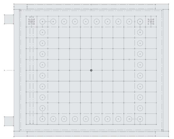
We created this master dimension sketch as the first step to reference when building our 3D CAD model. The middle 8 x 8 board is wrapped in capture spaces with the first and last columns reserved for promotions, as symbolized by the P.
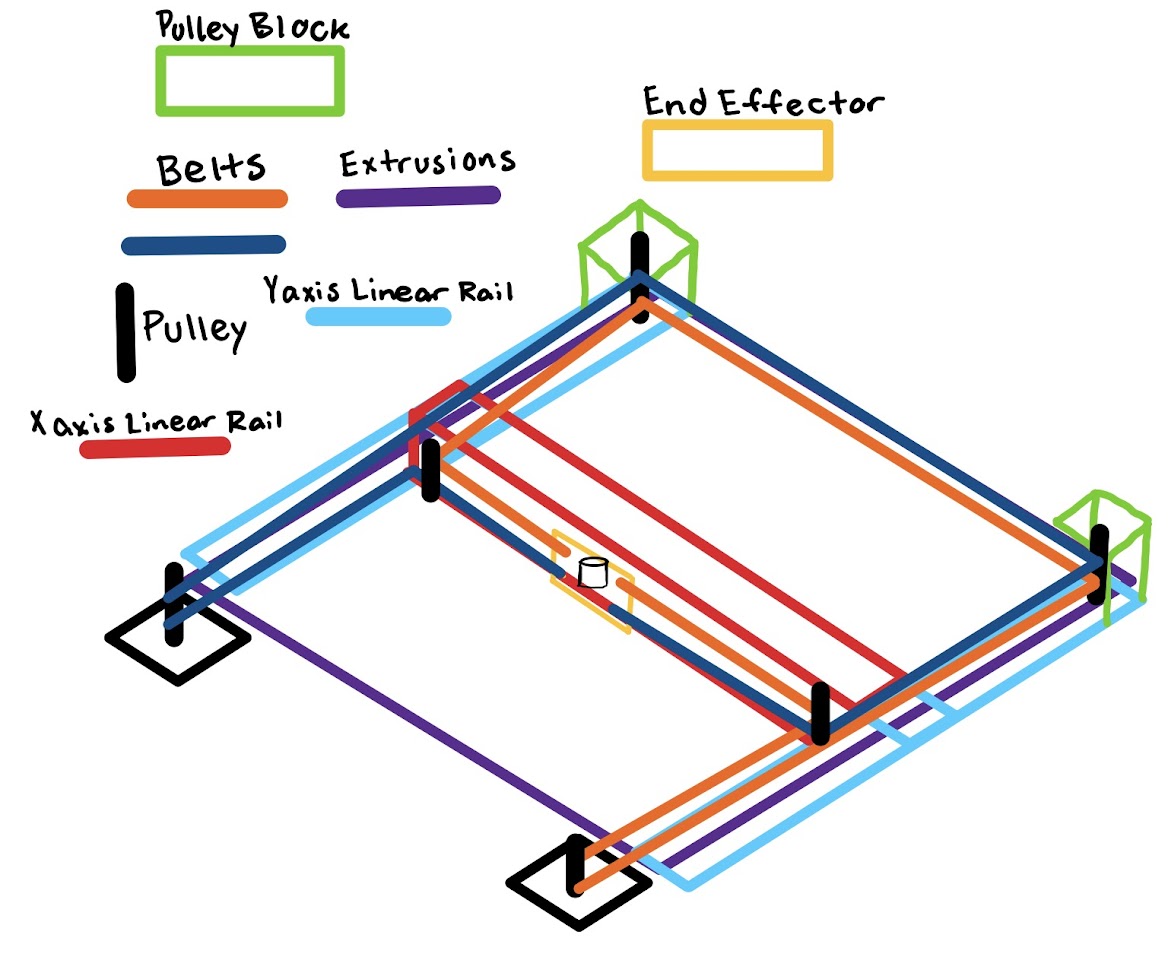
From here, we visualized what the gantry would look like in 3D, creating this sketch (below) to understand how the belts would be routed and where each of the mechanical components would be located (motors, belts, belt tensioners, end effector, pulley blocks). We planned the overall gantry architecture very early in the design process, allowing us to start and iterate on our prototypes of 3D printed brackets. One main design constraint was that the belts running along the Y-axis needed to be perfectly parallel to one another.
We then started a CAD assembly of the gantry to fully visualize and plan out our belt paths and locations, adding in the lengths of extrusions, connector brackets, motor mounts, and linear rails. The length and width of the gantry system were not set in stone at this point, as we hadn’t created prototypes of our end effector and pulley blocks to visualize the gantry’s max travel in X and Y.
Initial Gantry
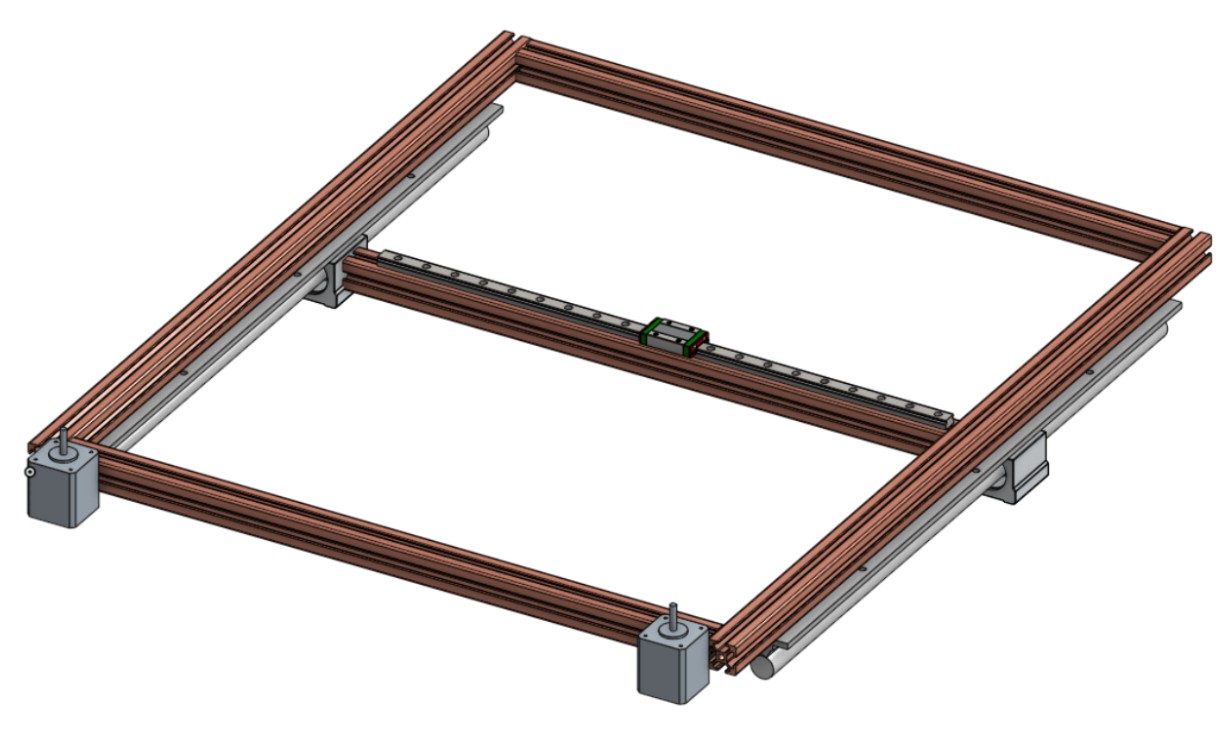
Our initial gantry idea consisted mostly of found parts around campus, such as the cylindrical linear rails, but we decided to buy a thinner and lighter linear rail since the cylindrical linear rails weighed a lot, and having two would cause us to have a heavy chessboard. Furthermore, these linear rails did not come with linear bearings, which were also very large. Because of this, we bought two 600mm MGN12H linear rails for our Y-axis and one 500mm MGN12H linear rail for our X-axis. Another change we made is that we moved our X-axis linear rails to be on the side of the aluminum extrusion rather than the top, as this would allow us to clamp the belts to the linear rail carriage, and hence restrain it easily. Also, the magnet system would be easier to implement if we did not have to worry about the board height; furthermore, we could easily extend the gantry range by simply adding a spacer block, which we had to do to maintain the needed range.
Continuing on design work, we designed the motor, idler pulley, and X-axis mounts. The locations of our pulleys were very critical and tied together all of these components due to our previous constraint that the belts along the Y-axis needed to be parallel to it. Starting with a rough sketch of the belt path in CAD, we were able to confirm these pulley locations and begin modeling.
Magnet Carriage
When designing the magnet carriage, some constraints that we had came up with consisted of the following:
- The Carriage had to not reduce the x-axis travel, or reduce the x-axis travel very minimally, to still reach all the target squares.
- The magnet had to be positioned in the center of the carriage to ensure that the final board was centered.
- The magnet had to have a predictable and repeatable movement path.
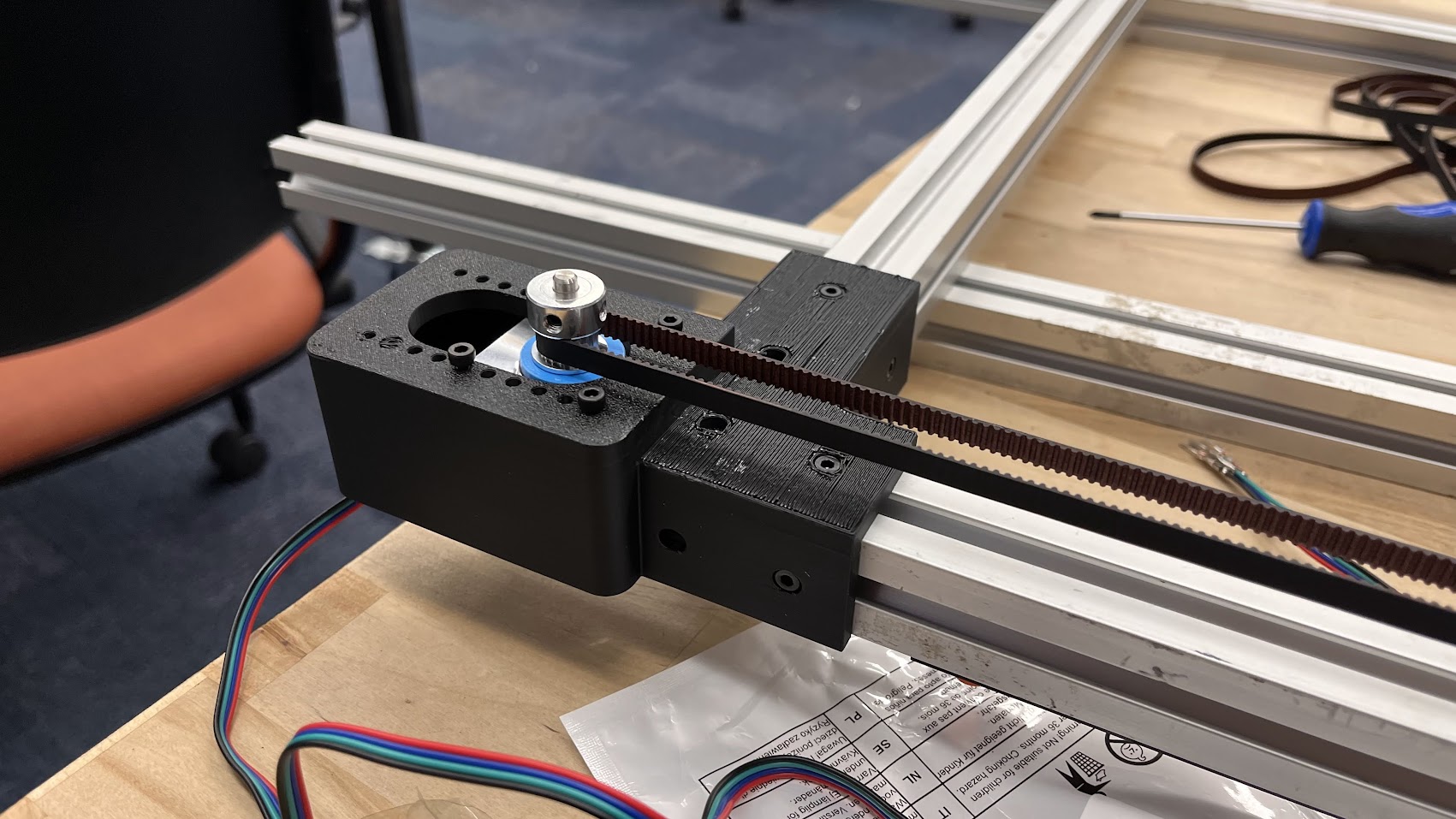
We decided that a rack and pinion system would be best, as it would be space-efficient, and its motion would be easily repeatable. We designed the servo horn to be easily press-fit into the pinion and held tightly in place by the servo screw. The rack design had to have a curve to it to ensure that the magnet remained centered on the carriage. The servo assembly would be bolted to the belt retaining system
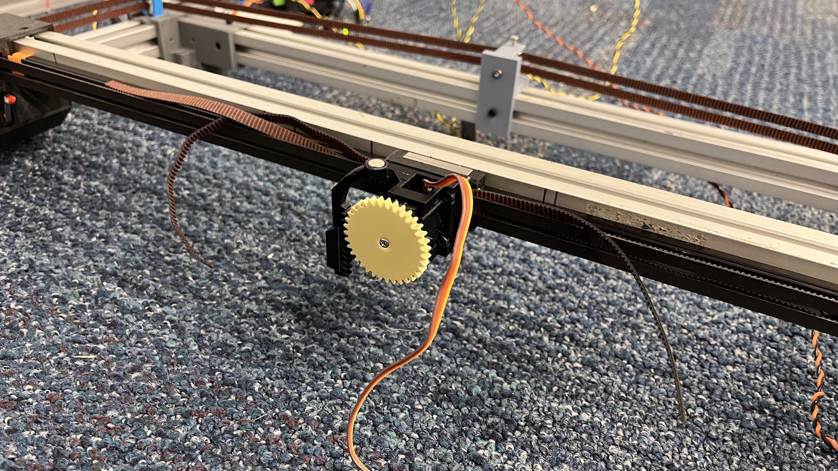
Our final end effector assembly.
Tensioner
When designing a belt system, the most important component is the tensioner, which is because it is very difficult to predict the exact length of the belt we need. Having a loose belt causes inaccuracies in the final movement end effector and slippage on the drive pulley. Our initial belt-tensioning system consisted of adjustable motor mounts (shown below on the left) and a small tensioner to fine-tune the tensioning (shown below on the right in the center of the extrusion).
The issue we ran into was that we could not tighten the belts properly. We tightened the belts as much as we could using the motor tensioner, and barely slipped the belt back on the pulley but the small tensioner couldn’t pull the belt to properly apply tension. Instead, we decided to create three tensioners for the belt, two on the corners opposite the motors, and kept the same one in the middle.
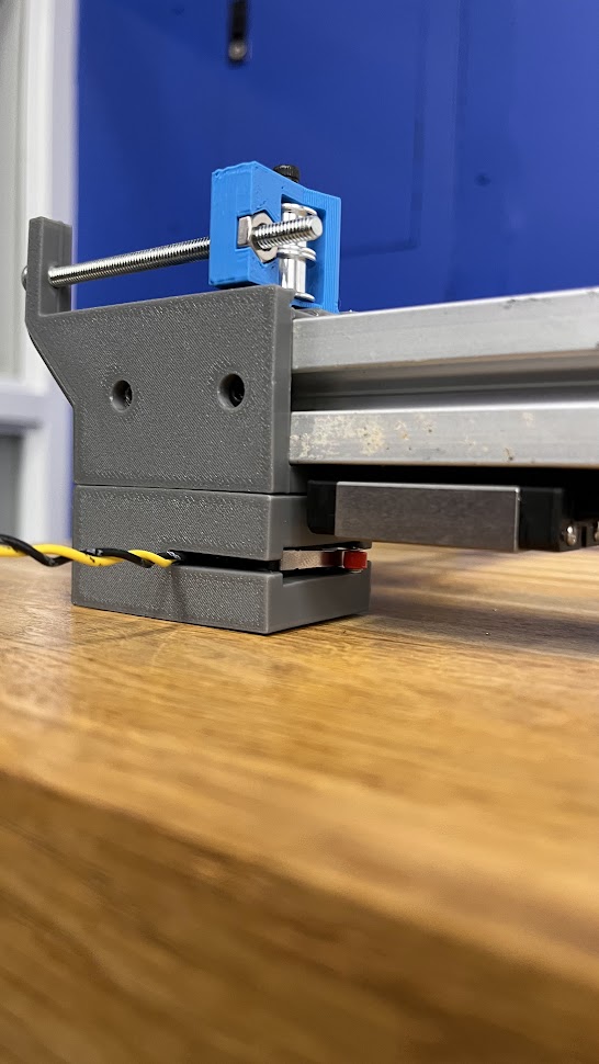
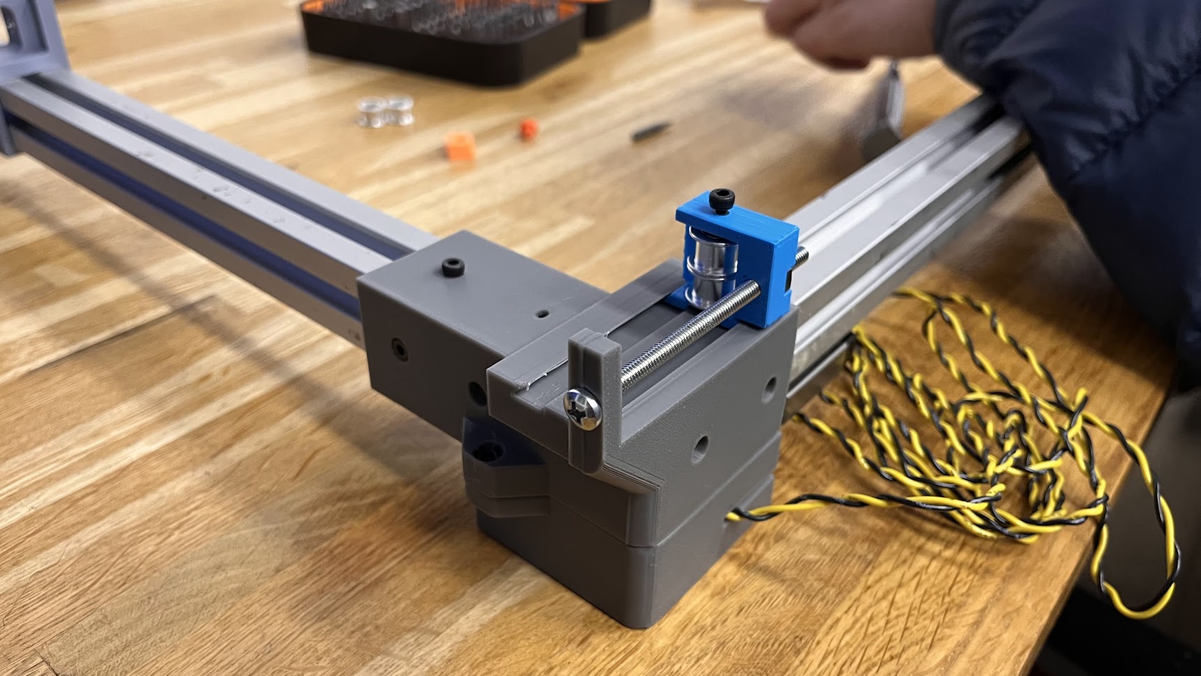
Having a tensioner governed by a screw and a nut was far more ideal, as it would allow for easier tensioning since it could be easily adjusted, and the high mechanical advantage offered by the screw and the nut allowed us more control over the belt tensioning. Our tensioner design can be seen below, where the belt is not yet tensioned.
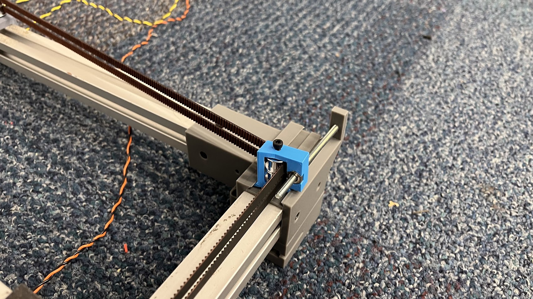
The design consisted of the pulleys being pulled inward by the tension of the belts, and the nut and bolt restraining them and dictating the belt tension. The dovetail rails restrain the tensioner laterally, preventing the bolt from widening its mounting hole or bending. For our tensioning needs, this was adequate, but the small PLA bolt segment connecting the bolt to the corner was starting to bend and deform toward the center of the board, and the blue tensioner segment was also starting to rotate, since the dovetail parts had play between them. If we had more time, we would redesign these blue parts to be more robust for longer-term use.
Board
When designing the board, we had to ensure that it could be easily readable at a glance and it could be easily readable to a new player. Some considerations that went into my design include:
- The player must identify squares and easily distinguish black and white squares
- The player must understand where the captures go and in what order to place them.
- The player must understand what promotions have taken place and available promotions.
- It had to look visually appealing
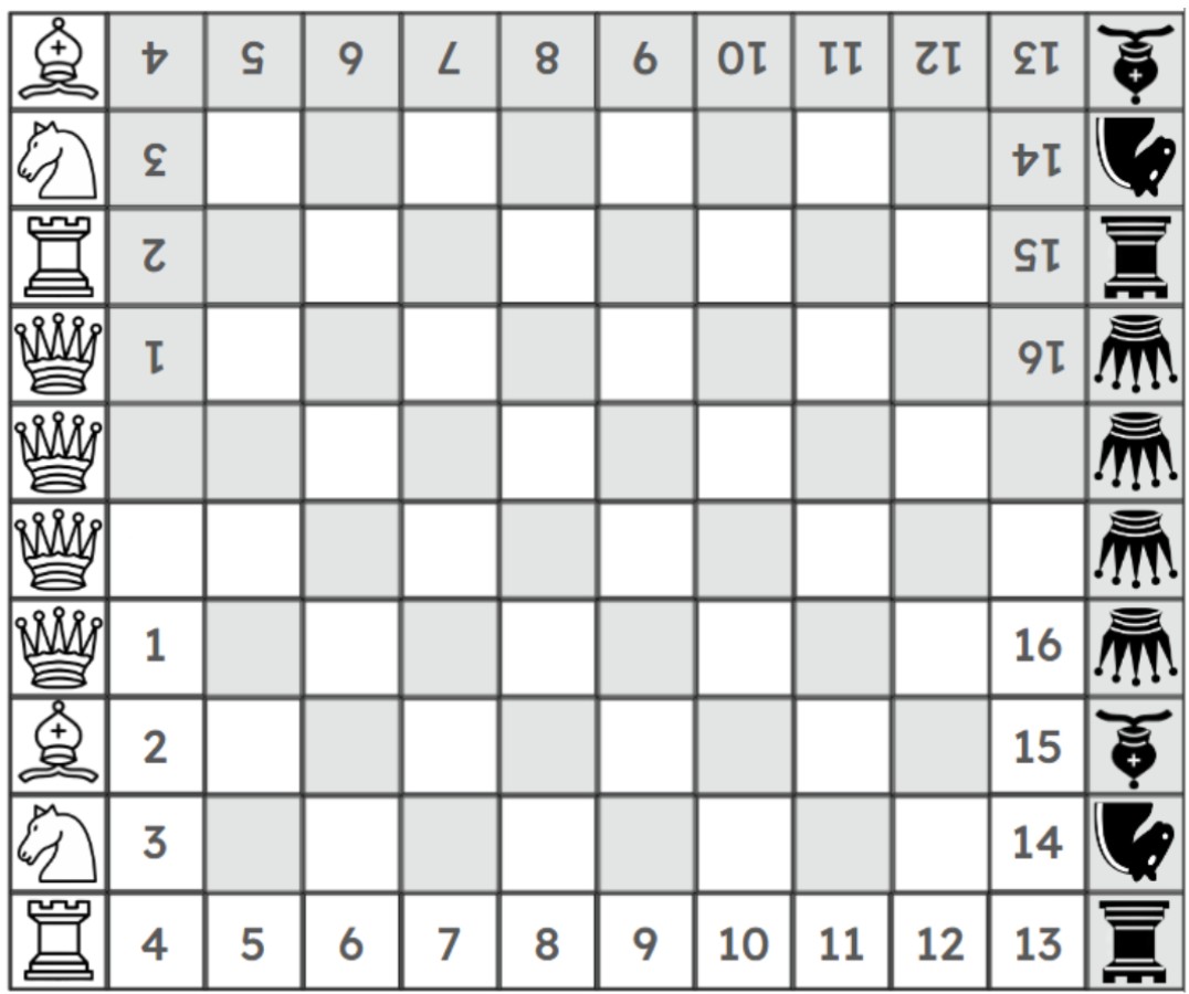
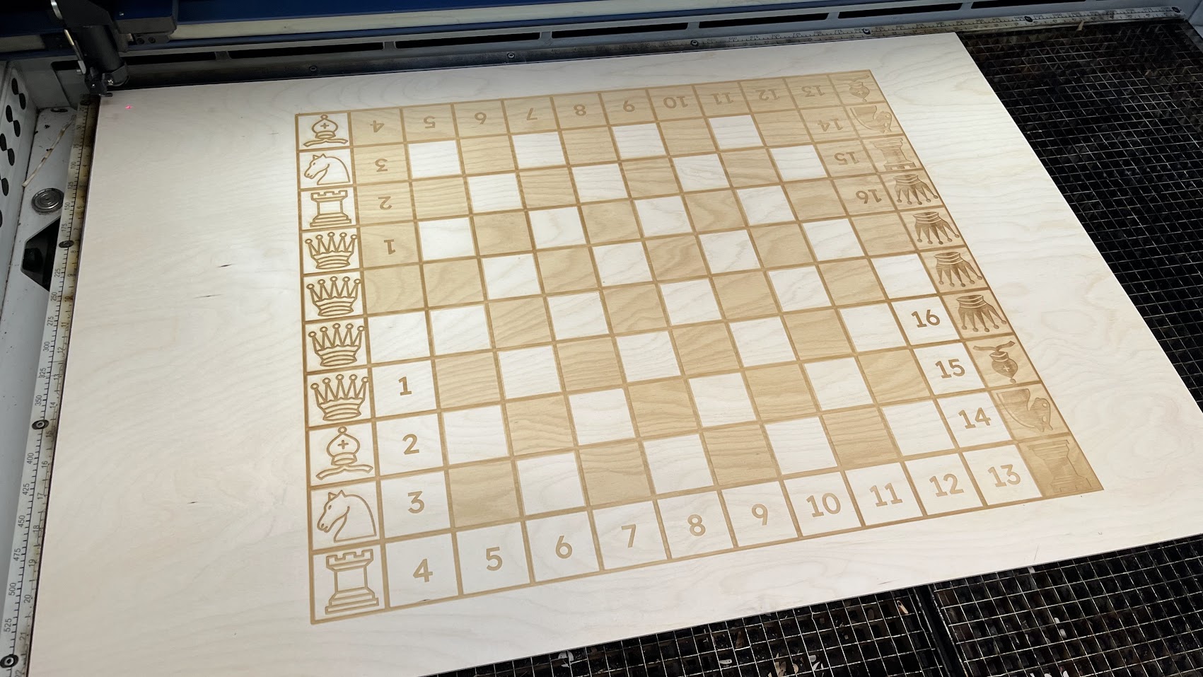
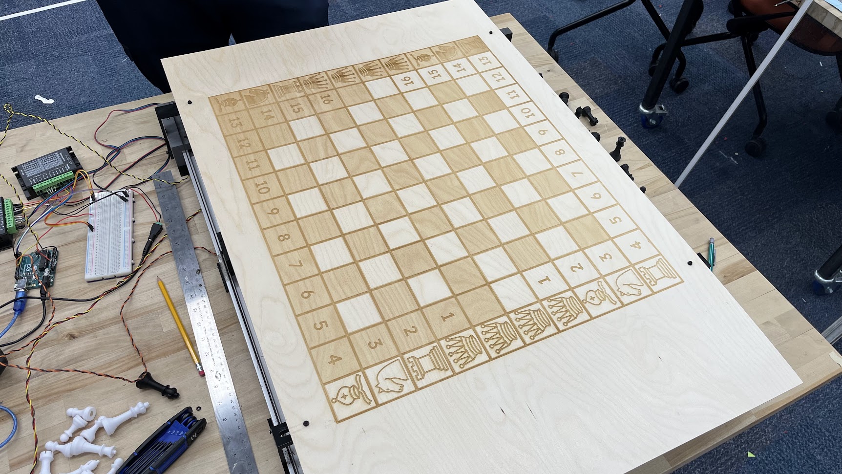
We decided to use appropriately colored numbered squares to distinguish captured pieces and the order in which captured pieces go in. For promotions, we used colored squares with piece icons for each available promotion piece. From the icon, a player can tell what promotions have been performed and available promotions to be performed. From online data, we concluded that 97-99% of promotions are queens. In the top-ranked games, promotions only occur in 1.5-5% of games, so using that data, we decided to have 4 queen promotions and 2 of every other promotion, to cover all edge cases and unexpected moves. To make the board visually appealing, we decided to raster a piece of clean birch wood with our design. Our design could not be very deeply engraved, so to give the appearance of a more deeply engraved design, we decided to add some depth visually. This was done by creating a CAD model of a chessboard, with elevated squares, and then taking a screenshot to use as our board design. We then imported all the icon images and numbered each square in Google Slides, and exported it as an SVG, which can be seen below.
To cut our big chessboard, we had to use the big Babson Foundry laser cutter. When performing test-cuts, we realized that only the laser cutter did not properly process our file and rastered everything evenly, and all the numbers and icons were not visible. This caused us to have to split our file into two passes, which increased our raster time from an hour to over two hours. The result at the end was absolutely stunning, and can be seen below.
Pieces
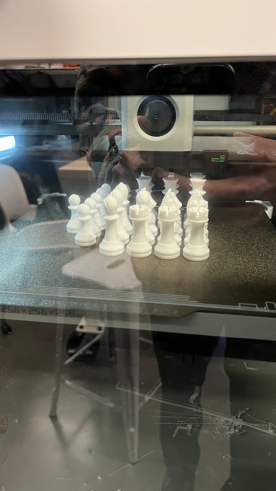
The chess pieces were obtained from a source online, which optimized the chess pieces to be 3D printed, while not severely altering their appearance from the default. We altered these downloaded pieces by adding press-fit magnet holes and scaling the pieces to fit our needs. We then 3D printed these pieces using a 3D printer with black and white filament.
Side Panels
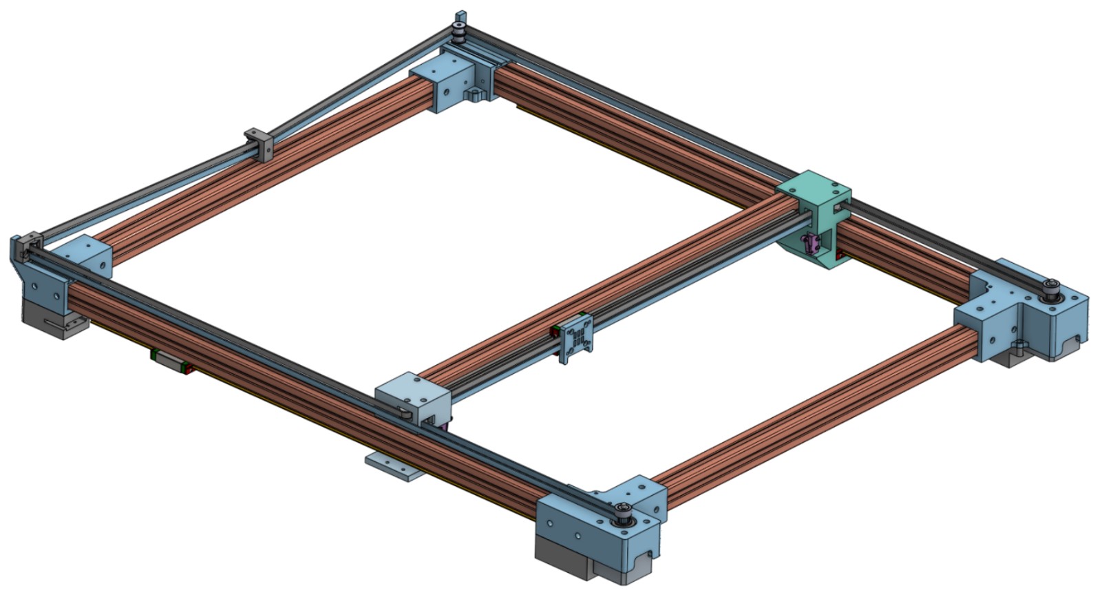
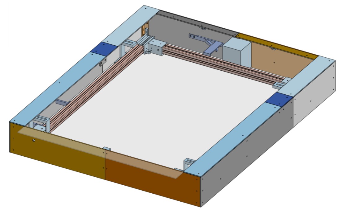
To hit our goal of having a magical chessboard, we had to have side panels to conceal all the magic. Since we attached the board by hand, this caused us to have a slight rotation in the board. Also, we did not cut the board to be fully square, and the chessboard was not fully centered on the board. If we were to do this again, we would make sure to cut the board perfectly and to create jigs to mount the board perfectly, but because of our oversight, we had to create some unnecessarily complex side panels. To create our side panels, the only identical pieces were the side panels on the left and right, and every other piece had to be unique, due to our oversight. To create our flush side panels, we created a CAD assembly with mounting brackets. We then 3D printed all the brackets and laser-cut 1/8th inch black chipboard for our side panels. After doing so, we realized that we failed to account for the kerf of the laser cutter, and a small gap in the laser print sections revealed our bright pink 3D prints, ruining the magic. Our stretch goal of adding sensing to the board so we could detect true human movement would have required a lot more wiring than anticipated, so segments of the cover had to be redesigned and recut to account for this oversight. The CAD of the redesigned pieces can be seen below, along with a simplified version of our gantry system:
Fabrication
We were able to fabricate the entire gantry system in-house, using mostly 3D printed and laser cut parts. The use of 1-inch aluminum extrusions made the frame extremely rigid and resistant to twisting or bending, essential for keeping our Y-axis from racking during long travels. We used M3 hardware throughout the entire build and learned that M3 T-nuts could be used in 1-inch extrusions without a hitch!
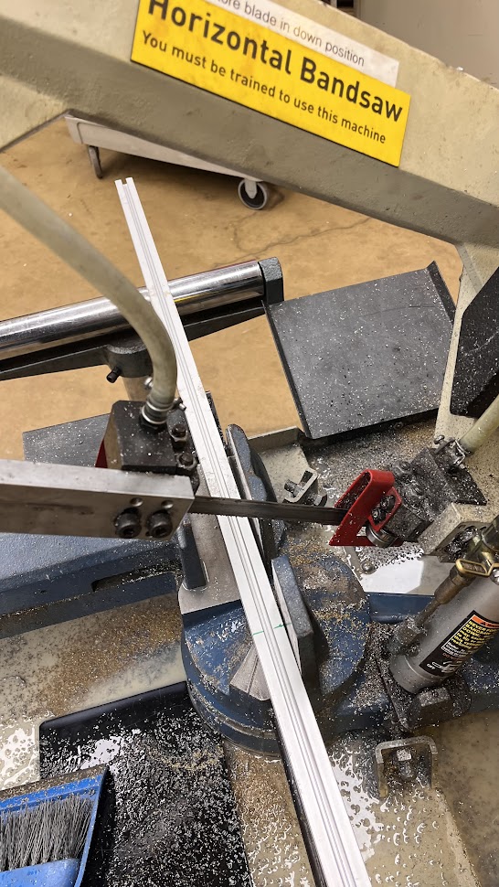
We began by cutting the aluminum extrusions to their final size on the horizontal bandsaw.
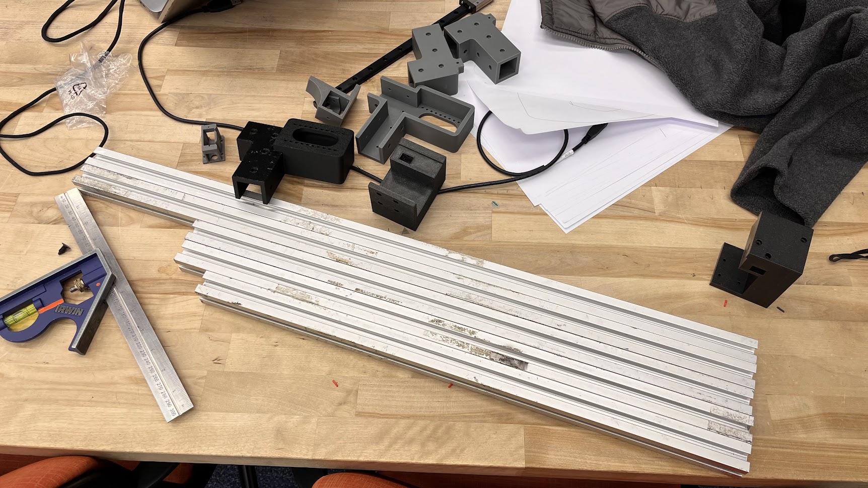
All our initial extrusions and 3D prints ready to assemble for version 1.
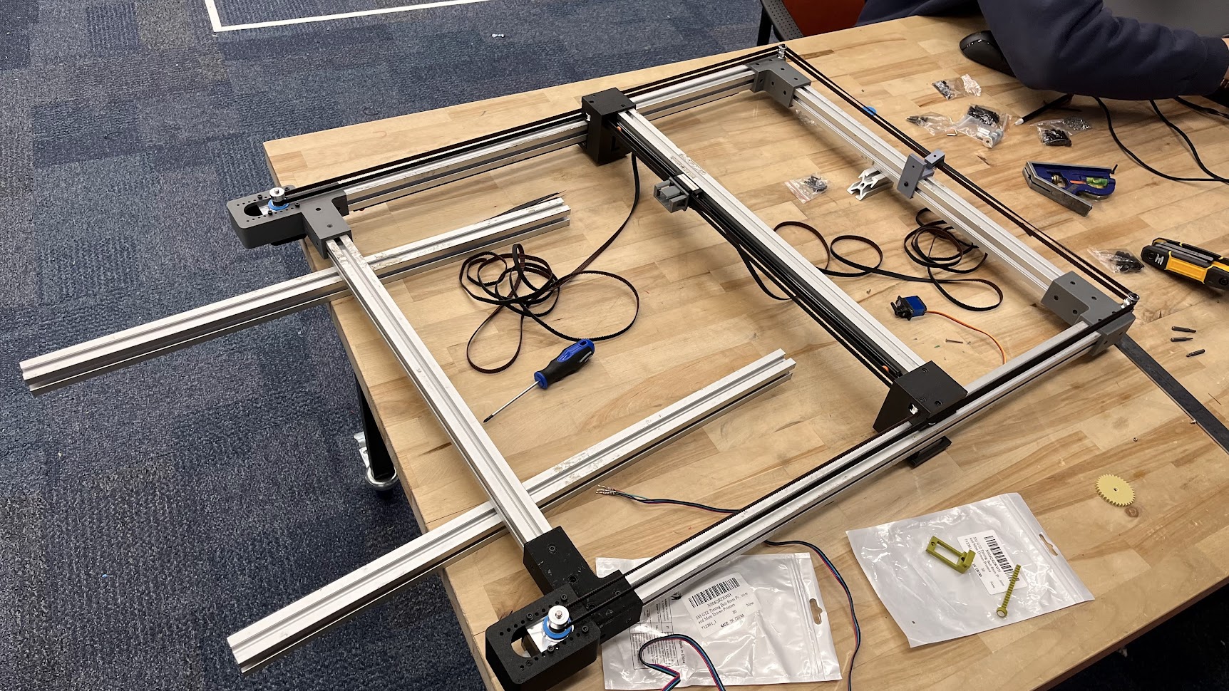
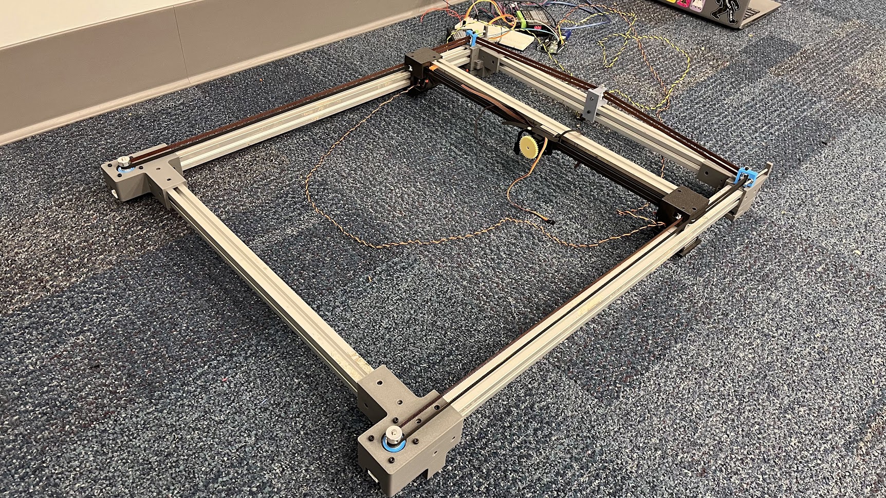
A few hours later, the gantry was assembled! As can be seen, the belts were very long at this point, as we weren’t fully sure about the size of the gantry. The stepper mounts were also designed with several mounting holes to manually tension the belt.

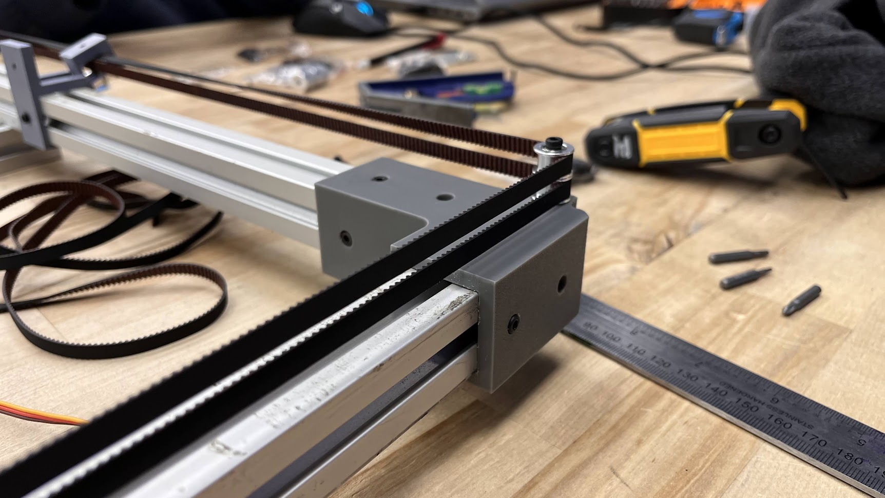
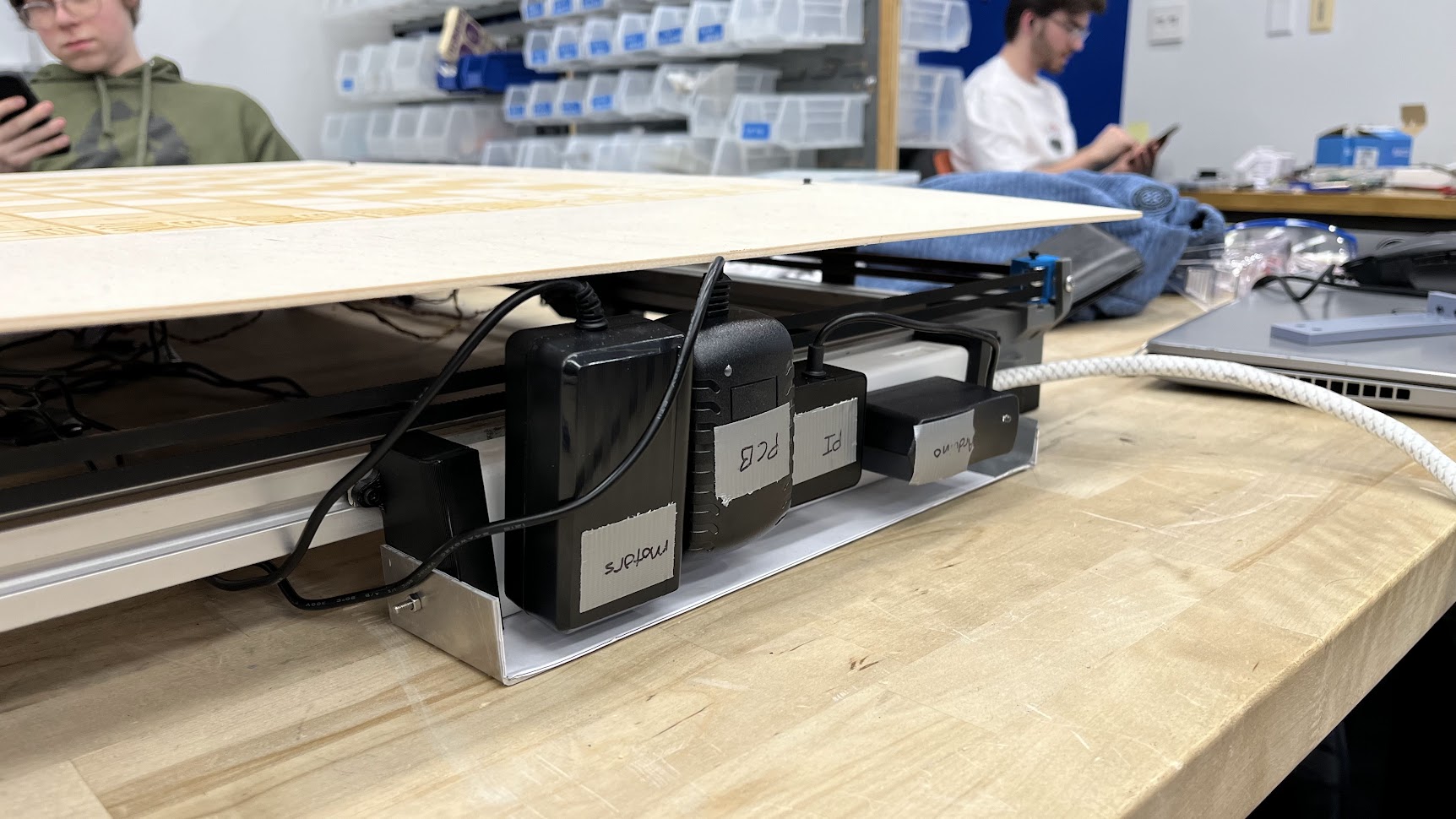
Our components in detail
For our next iteration, we refined all the parts shown to include mounts for limit switches, proper tensioners, and better printable motor mounts with feet.
From here, we were satisfied with the motion system in its current state and pivoted to working on the board and electronics mounting, and side panel design.
These parts needed a few iterations, especially because the board needed to be mounted at a slight angle for the playing surface to be aligned with the gantry.
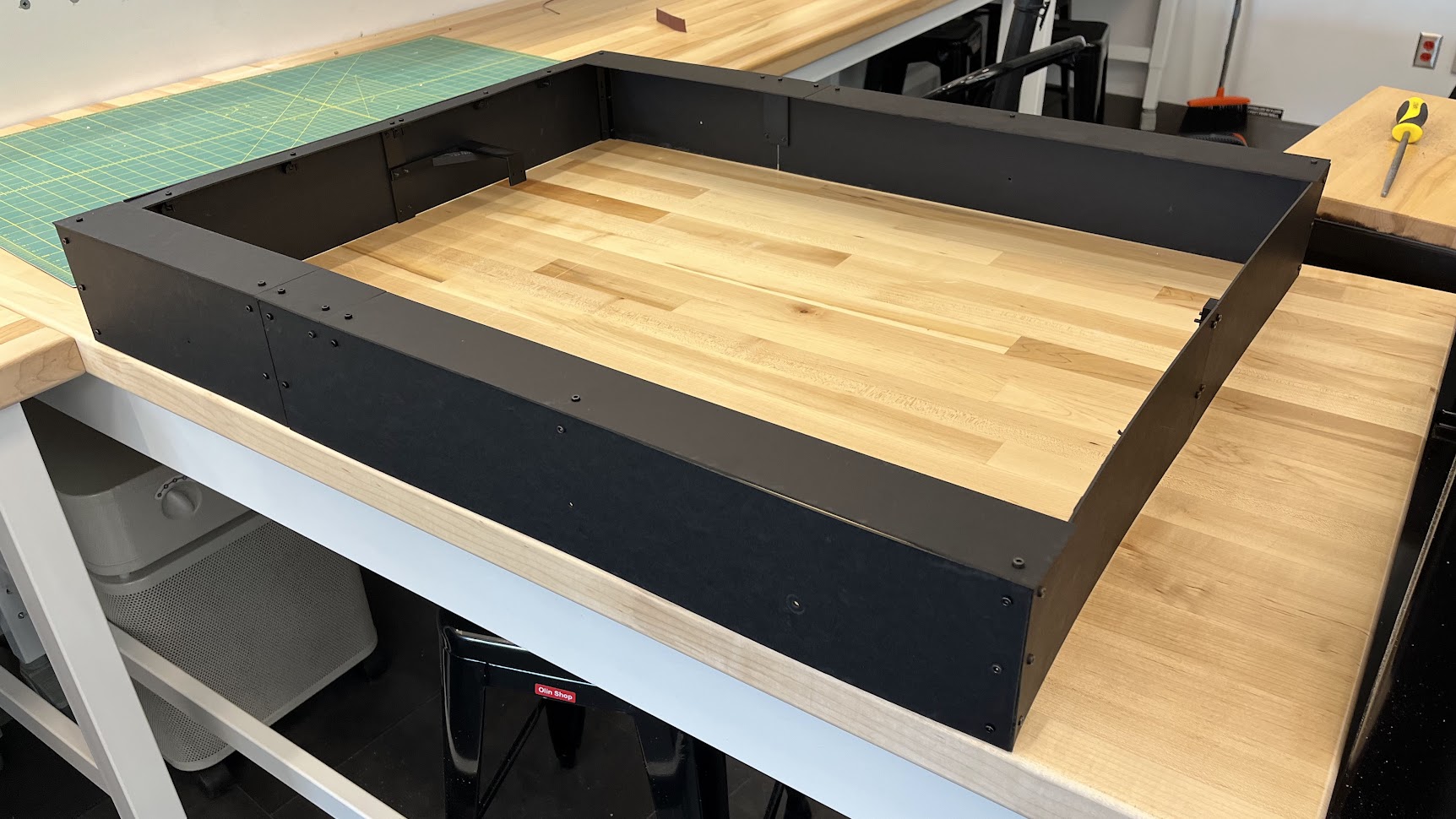
The final side panels
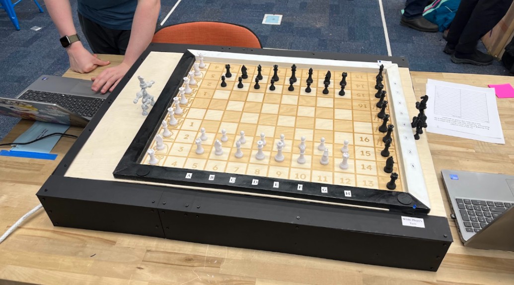
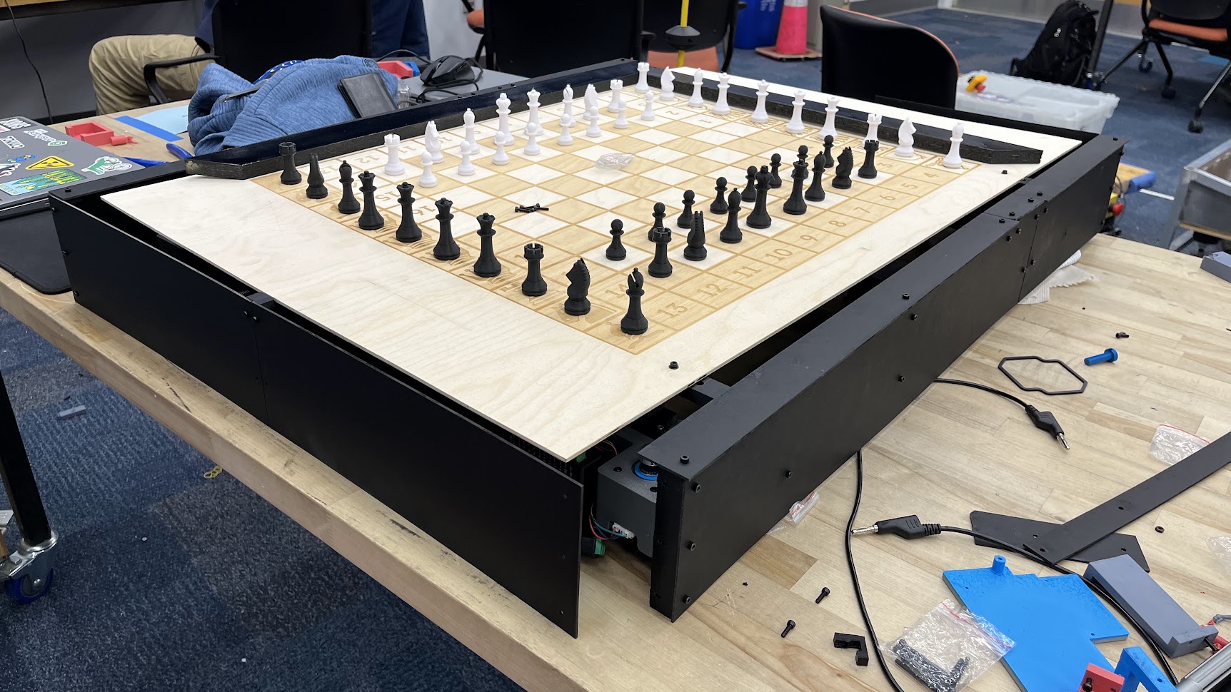
The full board assembled