Stepper Motors
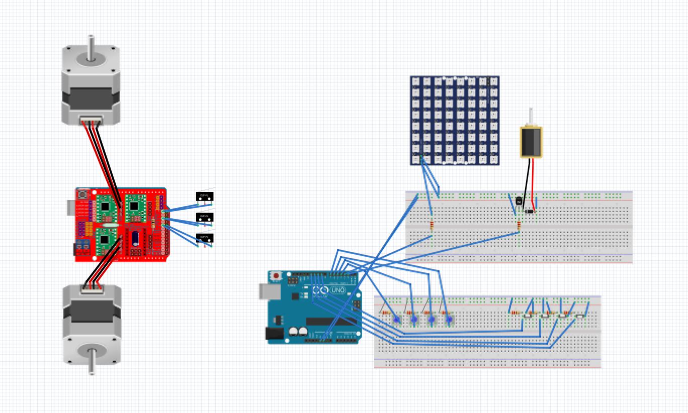
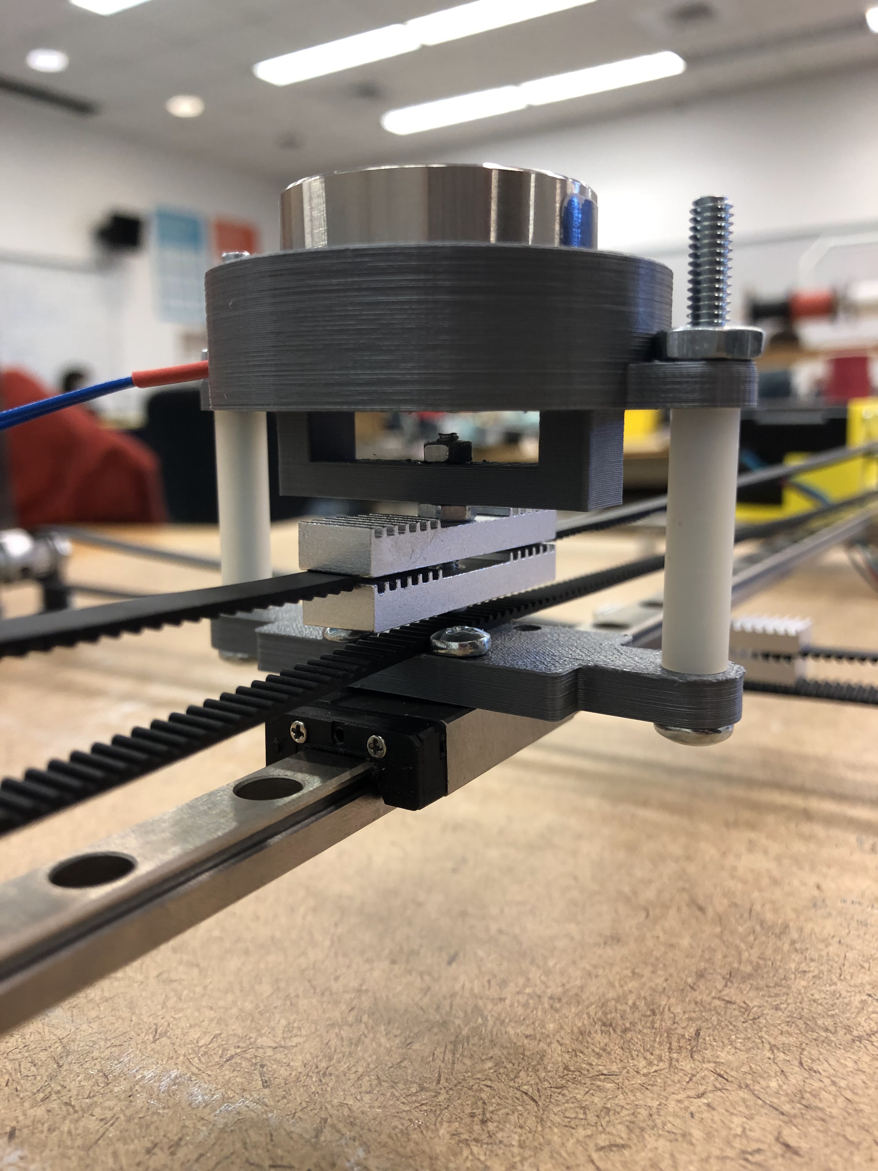
The Grandmaster Chess Board consists of a 2D gantry system which holds an electromagnet in order to move pieces. The electrical complexity begins at the two 12V stepper motors used to control the horizontal and vertical position of the magnet. Using a CNC shield (which connects to all necessary ports of an A4988 stepper driver chip), we were able to easily wire the stepper motors by attaching a female to female connector to the motor and connecting them to the shield. We also included 2 limit switches to precisely calibrate the position of the gantry.
Electromagnet
Once the stepper motors were functioning, we worked on the electromagnet. Our electromagnet system consists of a NPN transistor, a zener diode, and a resistor. The zener diode is connected across the magnet to ensure current flows only across the magnet. The magnet and diode are then connected to the transistor's C port. We then connect the B port to ground and the E port to a resistor between the transistor and the arduino's digital pin. Note: In our diagram (below), the electromagnet is shown as a solenoid due to the absence of an actual electromagnet being present in the diagramming software.
LEDs
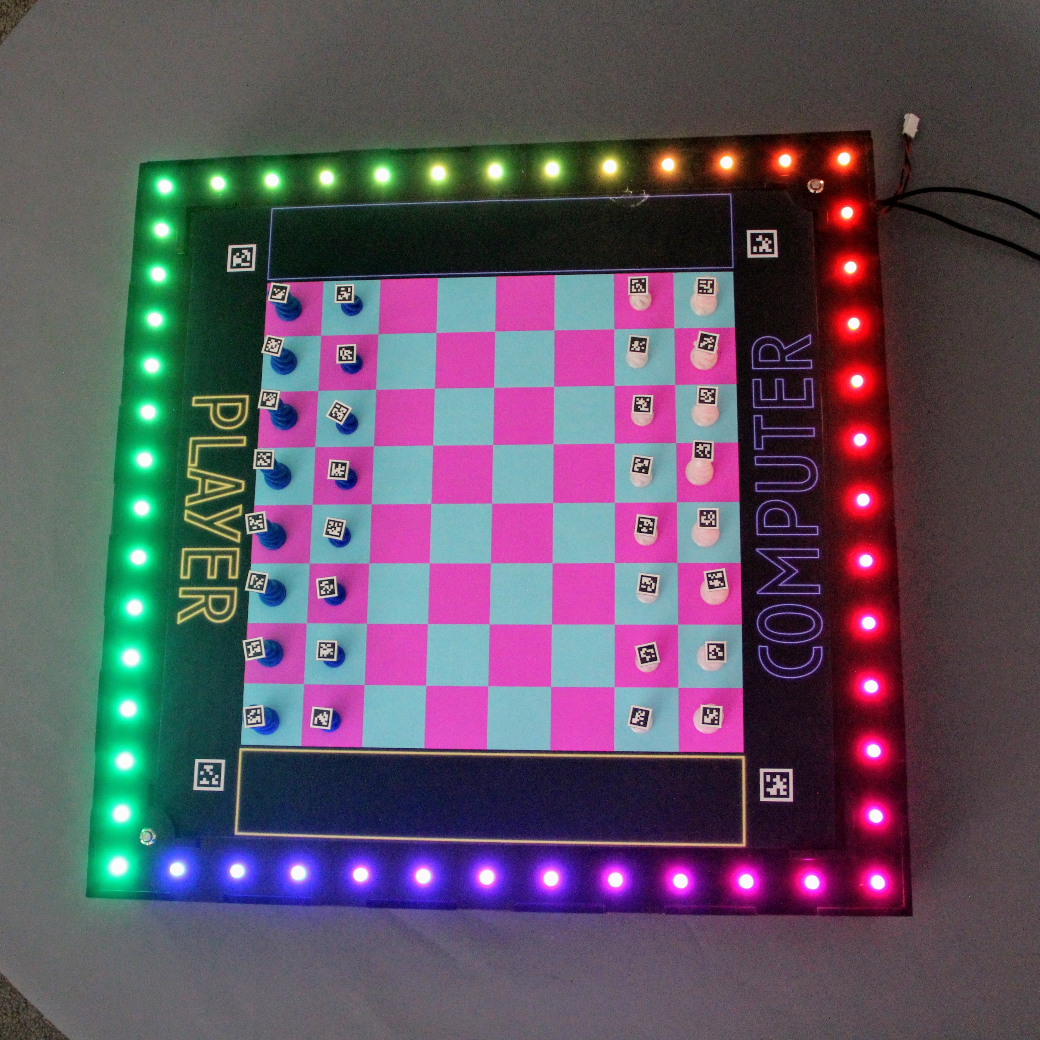
For aesthetics, we added NeoPixel W2811 lights which are individually-controllable leds that send commands to the adjacent LED. To wire these, we simply connected it to 5V and ground and connected a 300 Ohm resistor between the input of the leds and the Arduino digital port.
Buttons
Lastly, we have buttons that correspond to several actions within the realm of chess, namely start (to start a single player game), reset, and a button to indicate a move is over. The buttons were simply connected to power and a digital pin. The buttons also contain leds around the button which are separately wired.


