Electrical System
Electrical Requirements
To meet the goal of having a crab that walks towards you and hides its head into its shell when picked up, we needed the following electrical requirements:
- Motors that are powerful enough to move the weight of the crab forward
- Sensors that can tell where a person is
- A sensor to tell when the crab is picked up
- A servo to move the crab's head out of and into its shell
- A way to supply enough power to all of the above
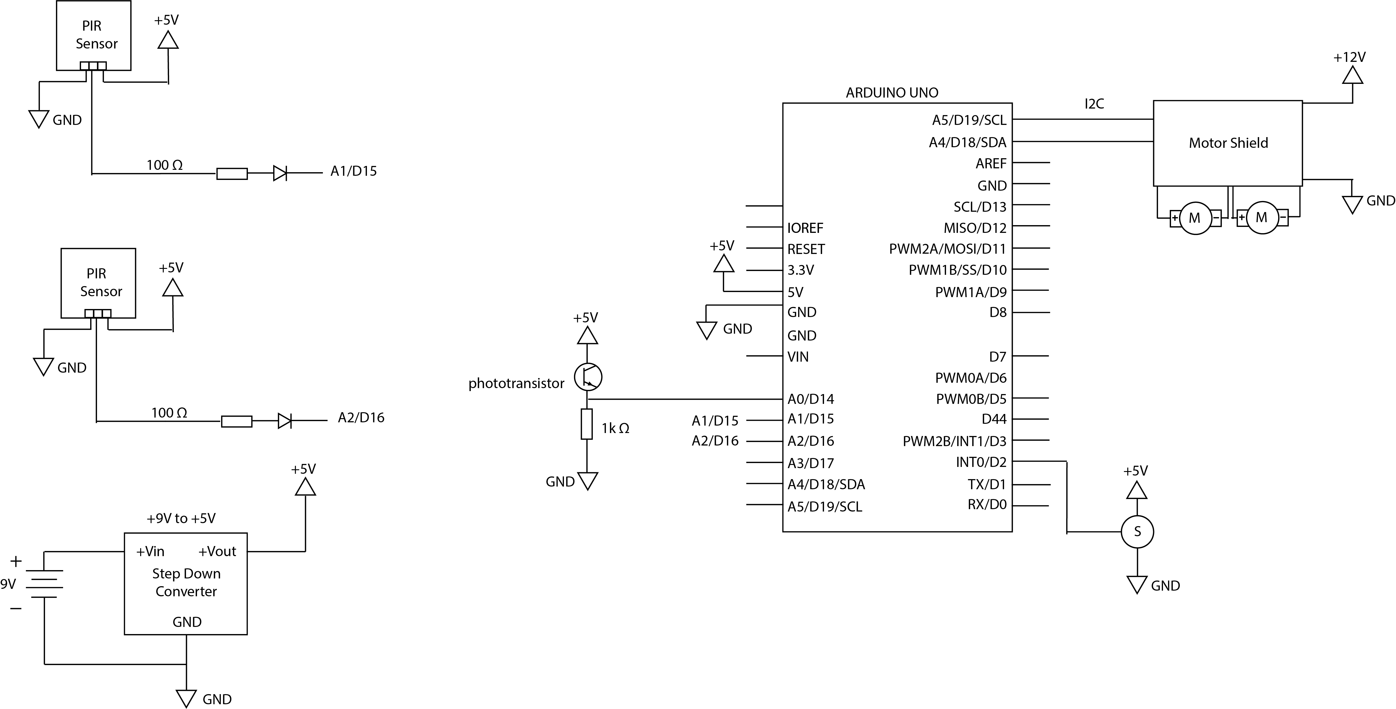
The electrical schematic for this system is shown.
Motors
To control the motors, we have a motor shield. The motor shield has a fully-dedicated PWM driver chip onboard that handles all the motor and speed controls over I2C. The Arduino is then able to communicate to the motor shield to apply power in pulses that effectively changes the speed of the motors. If we want the motors to go faster, we drive the PWM output to a higher duty cycle. If we want the motors to go slower, we drive the PWM output to a lower duty cycle. Note that the motors we used are rated for 12V so we used a 12V power supply for them (see Power section).
Sensors
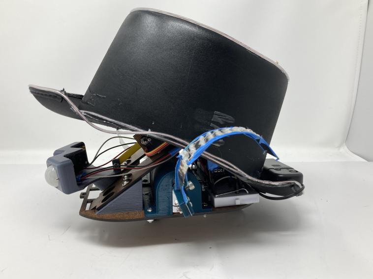
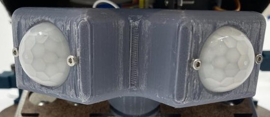
One of our requirements for our crab was to be able to tell where a person is. We accomplished this through Passive Infrared (PIR) sensors. A PIR motion sensor consists of two main parts: a pyroelectric sensing element and a Fresnel lens. The pyroelectric sensing element can detect infrared radiation. Note that human bodies emit heat energy in the form of infrared radiation. The white dome in front of the sensing element is a Fresnel lens. This lens focuses the infrared radiation onto the sensor.
We connected these sensors to analog pins on our Arduino that read the signals from the sensors. See the Software section to learn more about how we used them to detect a person.
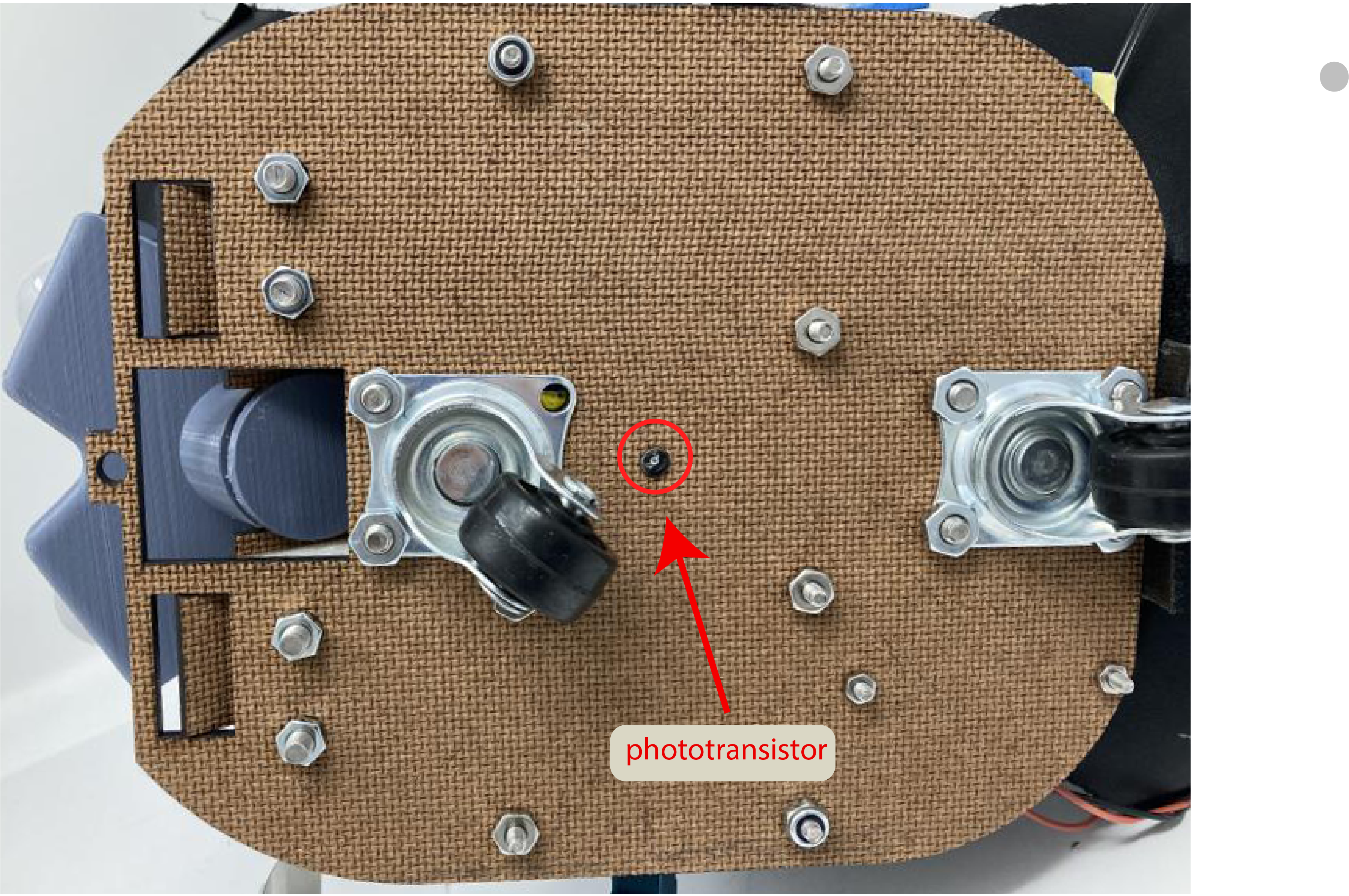
Another one of our requirements for our crab was to be able to sense when it has been picked up. We were able to do this through a phototransistor. The phototransistor is a transistor that responds to light striking it by generating and amplifying an electric current. Therefore, we could use the phototransistor to detect a change in light. By putting the phototransistor on the bottom of our crab, we were able to tell when it has been picked up. When it was on the ground, its body would cast a shadow beneath it, meaning that there wasn’t a lot of light hitting the phototransistor. When it was picked up, the phototransistor could be exposed to the light in its surroundings, meaning that there was more light hitting the phototransistor. By doing some testing, we were able to find a threshold reading that we used to determine of the crab has been picked up. To learn more about how we did this, see the Software section.
Head Movement
When the crab is picked up, it retreats its head into its shell. In order to make this movement, we used a servo combined with a slot slider mechanism. This servo was controlled by a digital input on the Arduino. Therefore, to move the head, we programmed the servo to move between 0 and 180 degrees. See the Software section for additional information about the sensing and logic.
Power
To power our crab, we have two sources of power: A 9V battery and a 12V power supply. In the schematic, we can see on the bottom right a 9V battery connected to a Step Down Converter. This Step Down Converter converts the 9V to 5V. This 5V powers the arduino, the PIR Sensors, the phototransistor, and the servo. Note that even though the Arduino Uno has a built-in low drop-out voltage regulator, we opted to use an external switching regulator due to it being more efficient.
In the schematic, we can see on the top right that the motor shield is powered by 12V. This 12V comes from a power supply and is only used to power the motors. This is due to the operating voltage of the crab being 12V.
Design Process
Testing PIR Sensors
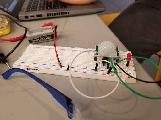
To first test the PIR sensors we connected the output to an LED as can be seen in the image of the breadboard. The PIR sensor sends high or low signals depending on if it senses anything. Therefore, at default this LED would be off, and when it detected a warm body, the LED would turn on. We used this setup as a means to test whether the PIR sensors worked as intended.
Testing Motors
When designing our crab, there were a couple of trade-offs that we had to take. The first tradeoff involved our motors. The motors that we first used were 6V motors with a 1:100 gear ratio. However, after mounting the motors to the crab, and driving them, we realized that the motors were not powerful enough to drive the crab forward. The legs/motors would simply stay in the same position.
Therefore, we decided to get more powerful motors. However, these motors required a higher voltage (12V) and drew a lot more current. When getting these motors we first tested them with a power supply at 12V. In doing so we found that they draw about 0.22 Amp when the leg is not in contact with anything, and they draw about 0.29 Amps when stalled. Given this high draw of current, we decided to use a power supply to supply the 12V instead of finding a battery solution. This meant that we had to tether our crab to a wall outlet, but we wouldn’t have to worry about a battery that quickly used up its capacity.
