Software System (Link to GitHub Repo)
Software/Firmware Requirements
- Read from PIR sensors to drive motors at differential speeds
- Read from phototransistor to extend and retract head based on orientation of robot
Firmware
We used an Arduino Uno Rev3 microcontroller and an Adafruit Motor Shield V2. Please refer to the electrical documentation for further discussion.
PIR sensing, PID, and differential drive
We use two PIR sensors to determine the location of a person. These are HC-SR501 PIR motion detectors, which output a digital HIGH or LOW depending on whether the sensor detects a difference in infrared between the left and right halves of the sensor. See electrical documentation for additional information.
The PIR outputs are fed into a PID loop based on the outputs of the left and right sensors, using similar logic as the mini-project 3 PID loop. The left and right motors are driven forward at differential rates depending on the output of the PID loop calculated based on the PIR sensors towards the person. Please refer to the source code for further detail.
For human sensing, we chose to use PIR sensing instead of a more advanced system (i.e., OpenCV) for two primary reasons. The first was the overhead cost associated with the hardware necessary for computer vision, such as a more powerful microcontroller and potentially an on-board camera. Secondly, the limited number of software people-hours (one E:C) and our goals to have multiple functioning software systems meant that it made more sense to choose a simpler, more straightforward human sensing system in the interest of other mechanisms.
Phototransistor and head movement
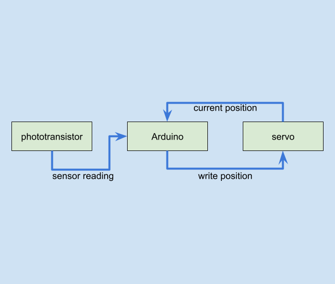
We use one HW5P-1 phototransistor to determine whether the hermit crab is upright or upside down. As discussed in the electrical documentation, the phototransistor outputs to a pin on the microcontroller depending on how much light is present. It is mounted on the bottom of the base plate, facing toward the ground. Thus, when the hermit crab is upright, the phototransistor is shadowed, and it outputs below our threshold. When the hermit crab is lifted or upside down, the phototransistor senses the increase in light above our threshold. The logical comparison between the phototransistor’s moving average and light threshold is done by the software on the Arduino.
The threshold was chosen so that when any light reached the phototransistor, the threshold would be exceeded. We encountered a roadblock where noise from the phototransistor would inadvertently trigger the head to retract and extend, which was easily fixed by taking a moving average of the phototransistor readings (with the movingAvg library) to use for the logical comparison to the threshold.
A servo is used for the head slot-slider mechanism. The servo has two states, one for head in and one for head out (at 0 and 180 degree positions). Based on the phototransistor output and the current state of the head, the Arduino writes to the servo to flip the state of the head.
We chose to use a phototransistor instead of a more complex orientation sensor for simplicity. Because we placed the phototransistor in a location where it would always be shadowed in the upright orientation, we were able to add logic in software that mapped the phototransistor output to the orientation of the hermit crab.


