Electrical Subsystem
How we use power to go vroom.

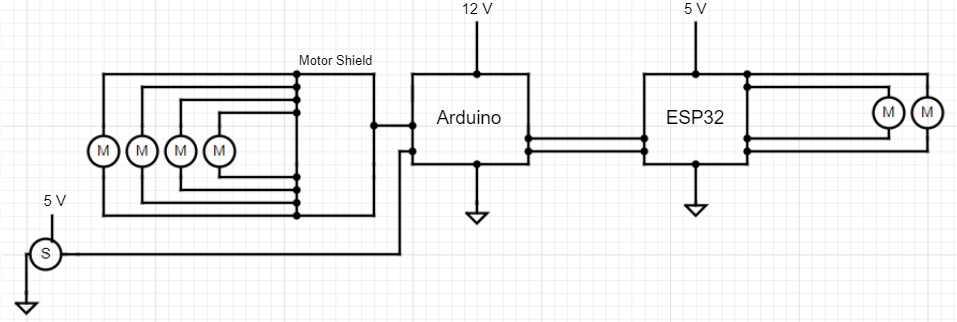
We created a system which takes input through WiFi and instructs the motors on both the main car itself and the projectile launcher what to do. The system is outlined in the diagram below.
Components
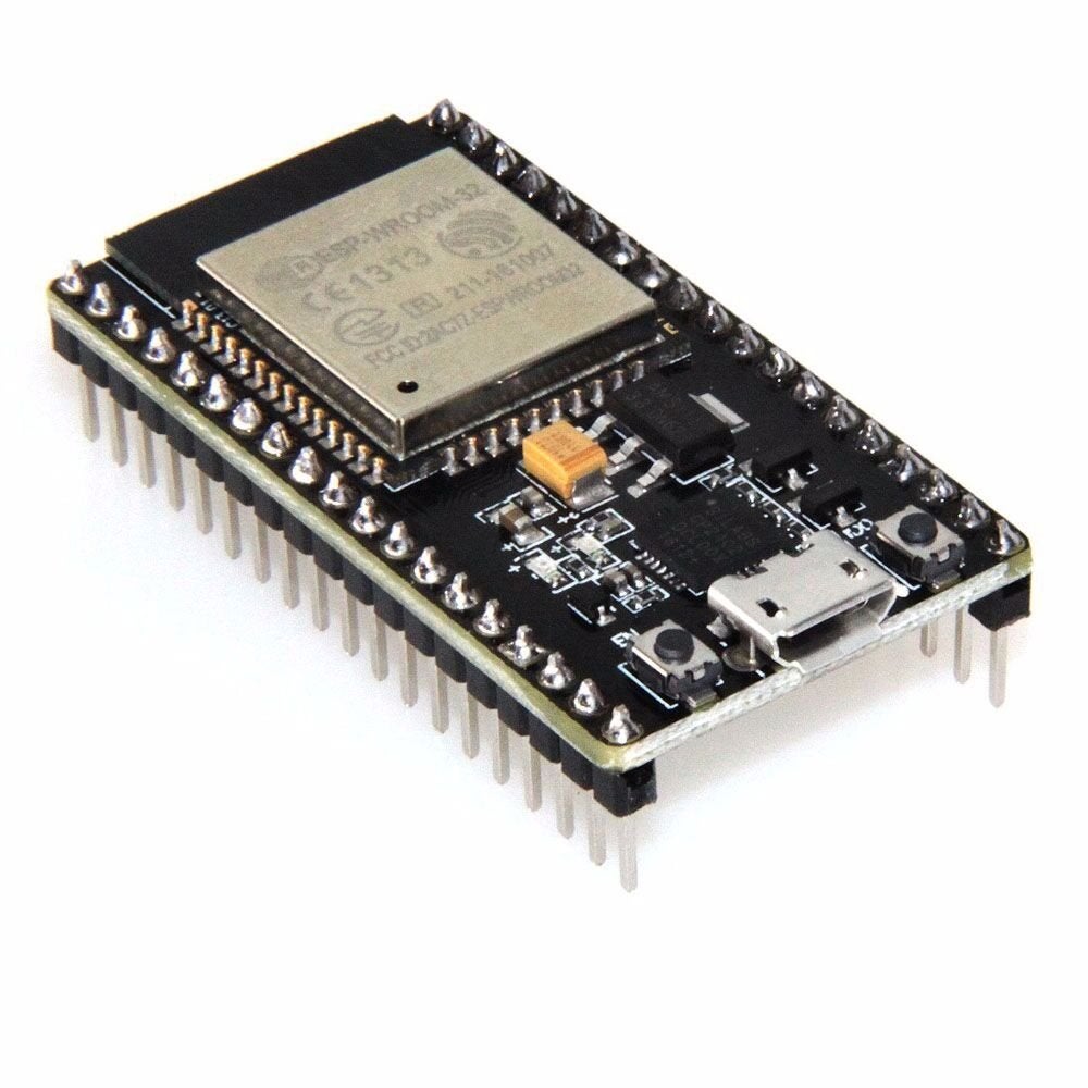
ESP32: This microcontroller creates the web service and interface for the user to control the ROV-R. When powered, the ESP32 establishes this web service. When the user accesses this web service and inputs the keys to move the ROV-R, the ESP32 receives that information and translates it to information the Arduino can understand, before serially transmitting that data. The exception to this is when the “Firing” button (spacebar) is pressed, since the ESP32 interfaces with the motors that commence the firing sequence. When the spacebar is pressed, the ESP32 sends PWM signals to the motor that pushes a marble into the flywheel mount and the two motors that are spinning the flywheels. Once the marble is launched, the flywheels stop and the motor that pushed up the marble retracts.
Arduino Uno R3: This microcontroller was used to interface with the motor shield that controls the wheels. It takes input through serial from the ESP32, and depending on the input calls certain functions that make the ROV-R move in different ways. For example, there are functions that make the ROV-R move to the right, left, forward, diagonally, and spin.
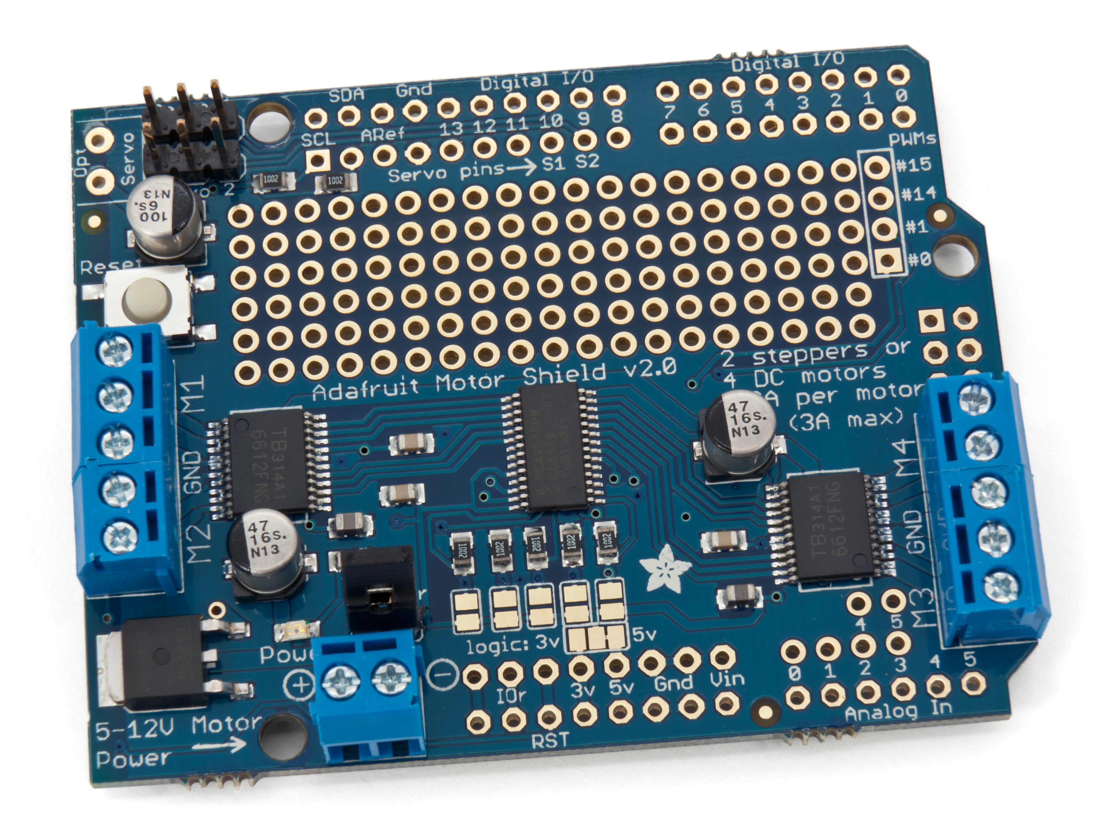
Adafruit Motorshield v2.3: This motor shield interfaces the motors that drive the ROV-R. The Arduino instructs it how to drive each motor.
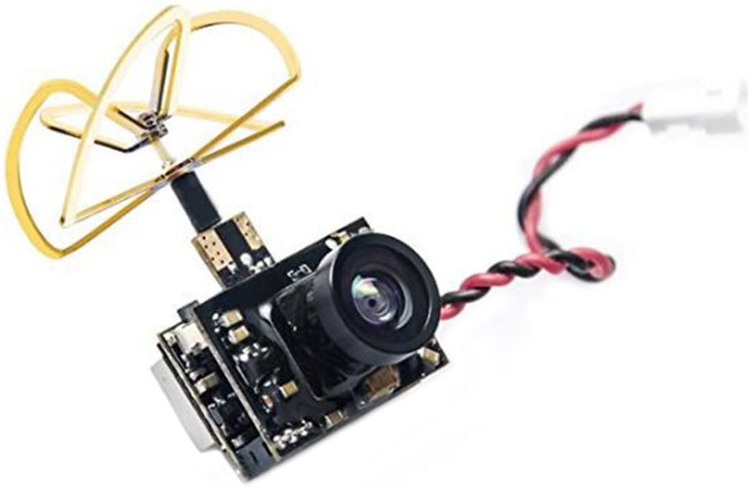
5.8G OTG FPV Camera and Receiver: This camera transmits live video of what it captures to a receiver. Both the camera and the receiver can broadcast signals for 50 different channels in the 5.8GHz range, which means that we can optimize for the best channel if another channel is being used by someone else or has too much interference. Originally, we planned on interfacing the camerafeed with the webservice on the ESP32; however, there are no cameras that interface with either the ESP32 or the Arduino very well; there will always be a sacrifice in quality and budget. As a result, we went with an FPV camera that works over radio rather than WiFi.
Power System
The system is powered with two 12V LiPos. One 12V LiPo powers all the DC motors, which all require 12 volts. The other 12V LiPo powers the other electronics. The Arduino takes 12 volts, since it has its own voltage regulator; however, the ESP32 and camera require 5 volts. As a result, we use a voltage step down (Pololu 5V, 2.5A Step-Down Voltage Regulator) to power these components.
Originally, the system was powered with one of the 12V LiPos for the motors and one 9V Energizer battery to power the Arduino. It was originally configured in that the ESP32 and the camera were both connected to the Arduino's 5V pin to get power. While both components did need 5V that the Arduino could provide, they both have decent current draws. The ESP32 requires 40 mA (which was harder to achieve as the battery died overtime), and the FPV camera needs between 250 and 500 mA, which is not possible through the Arduino, which has an output current of less than 100 mA. As a result, we switched to using a 12 volt LiPo with a 5 volt step down voltage regulator.


