Mechanical System
"The parts of the robot you can touch without breaking it. Because if you do that with electrical parts you might break it." -- Jack the MechE

In any robotic system, the mechanical system is always just as important as the electrical and software systems. There are two main portions of ROV-R that define the mechanical system: the chassis and the projectile launcher. The goal of the chassis was not only to provide a robust structural support for the whole robot, but to also house all the electronic components that were necessary to get the robot moving. The projectile launcher, which was part of the Minimum Viable Product, is designed to shoot marbles at high speeds.
Chassis
There are two parts to the chassis: the lower chassis and the upper chassis. The design of the lower chassis was designed based on a metal frame that was part of an omnidirectional wheel kit with which we started (linked here). This metal frame was adjusted from the original that came with the omnidirectional wheel kit. Our new design raised the chassis to minimize potential wires dragging on the ground. We also doubled the area of the chassis as we got more electrical components than our original size could handle. To fabricate this, it was designed as a flat plate in SolidWorks, cut from sheet metal using the plasma cutter, and the sides were bent in the metal shop.
The upper chassis, which houses our electronic components, was also designed in SolidWorks and then cut using the laser cutter on MDF plywood. On top of keeping our power supply and microcontrollers safe, it also acts as the ramp for our projectile launcher. We decided to give our projectile launcher a 30 degree incline so that the marbles shot can go a significant distance but also not fire too high above the robot’s line of sight.
Projectile Launcher
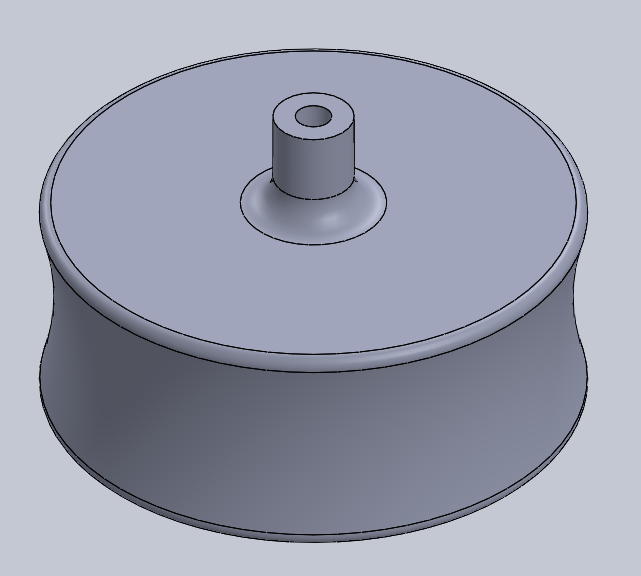
The projectile launcher is composed of four main components: the flywheels, the flywheel mount, the ammo compartment, and the loading mechanism. The flywheels needed to be more of a complex shape and therefore 3D printing was the ideal method of fabrication. They were initially based on nerf gun flywheels but later optimized for our marbles and altered to better fit our motors. Once printed the outsides of the flywheels were covered in a layer of rubber bands and electrical tape to allow for the marbles to be gripped.
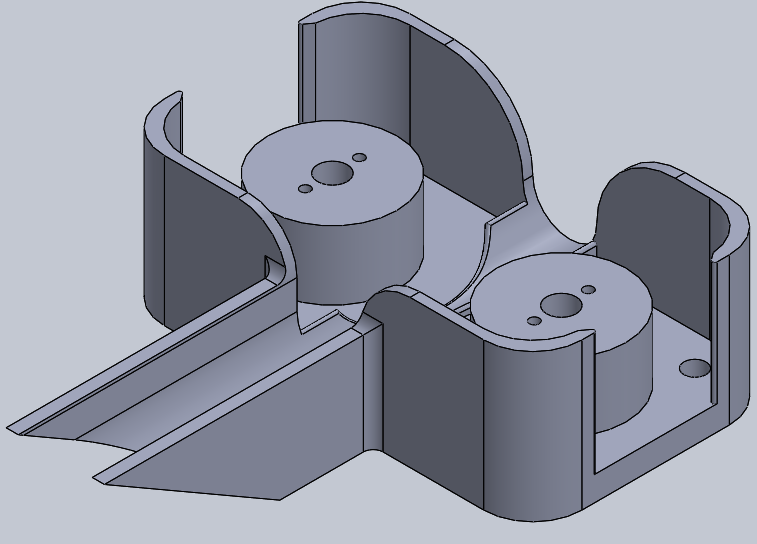
The flywheel mount is a thing of beauty designed in SolidWorks. This was designed again based on a mount for a nerf gun but optimized for our project. It includes a track for the marbles that goes between the spots for the flywheels that also accounts for the angle change between the bottom of the ramp and the top of the roof.
The ammo compartment was designed to hold up to 12 marbles and release one at a time into the projectile launcher. Once printed, it was attached to the flywheel mount using acrylic weld to ensure it would not move, meaning the marbles would always drop consistently in front of the loading mechanism.
The loading mechanism consists of a servo and a small cylinder connected by a joint. The servo is attached to the bottom of the flywheel mounts so that the cylinder will push a marble forward into the flywheels when rotated 180 degrees. This type of cylinder was chosen because it was the perfect size to push the marbles effectively and not allow for marbles to fall out of the container behind it. Given more time, a mount would be created to hold this more firmly in place.


