Overview
Reuse Rebuild React is a 7’x7’x4’ sculpture. 72 curved jellyfish (street signs and wood scrap) rise and fall fluidly within the bounding box of a wooden frame (deconstructed pallets) as nearly invisible strings tied to the jellyfish winding up above the viewer’s eyeline. The simple but elegant motion stands at odds with the origin and appearance of the materials - literal trash. Here’s how we built something from nothing:
The Big Picture
The jellyfish are attached with string to pulleys of different sizes. Consequently, when these pulleys are spun with the same angular velocity, the jellyfish will move at different linear speeds. To control this motion, nine unique pulleys are attached to each shaft and all spin together. A total of eight individually controlled shafts control 72 total jellyfish.
Contents
- One frame
- Seventy two jellyfish
- Seventy two pulleys
- Eight Shafts
- Sixteen mounts
- Sixteen shaft to mount interfaces
- Eight Motors Encoders
- Eight Motors
- One kinetic sculpture
Breakdown of Components
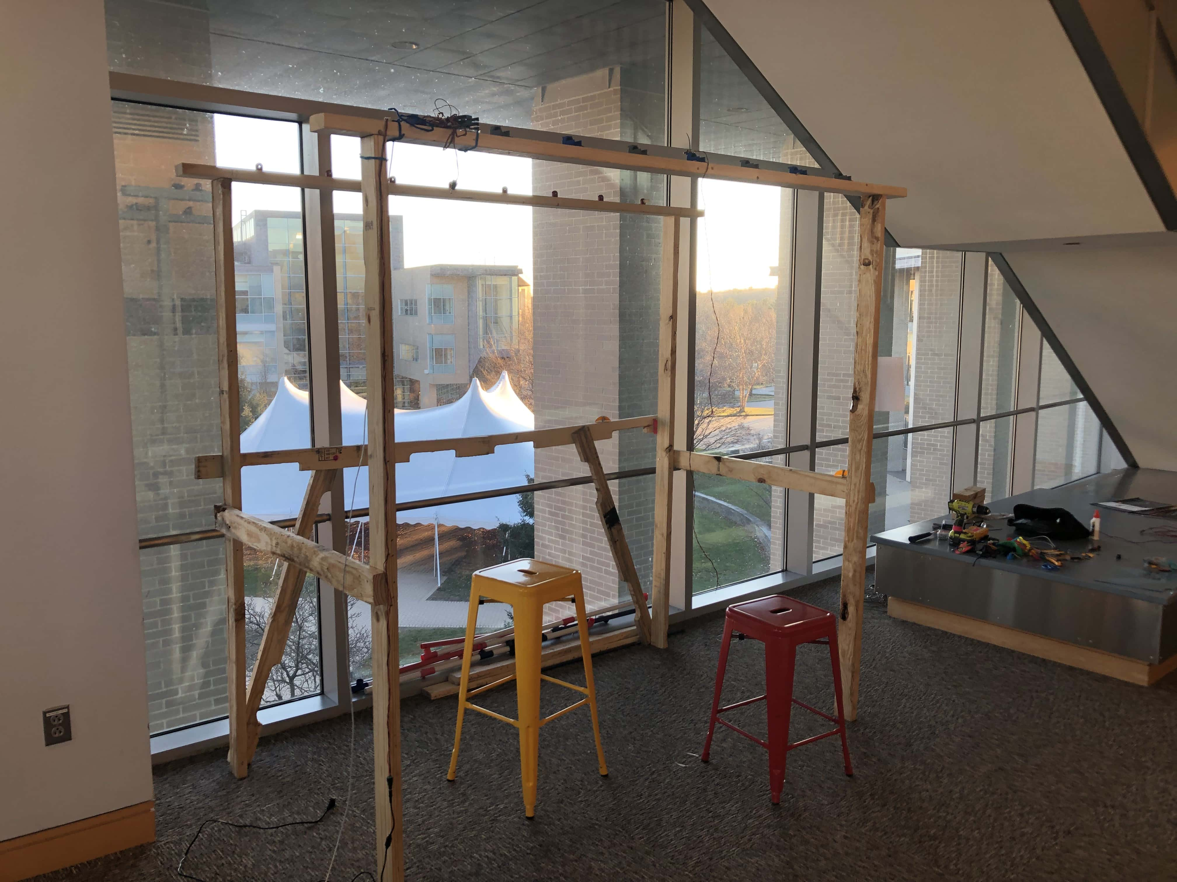
The Frame - to hold it all together
The frame is made out of sturdy wood (taken from discarded pallets). We first built two H frames to outline the depth of the sculpture. We then set the length by connecting two long beams across the top of each leg.
The mounts for the pink shafts attach directly to these two long beams. There is additional wooden bracing in the back. This allows for full visualization of the sculpture from the front and a largely unobstructed view from the sides.
The Jellyfish - Be Prepared to Stop
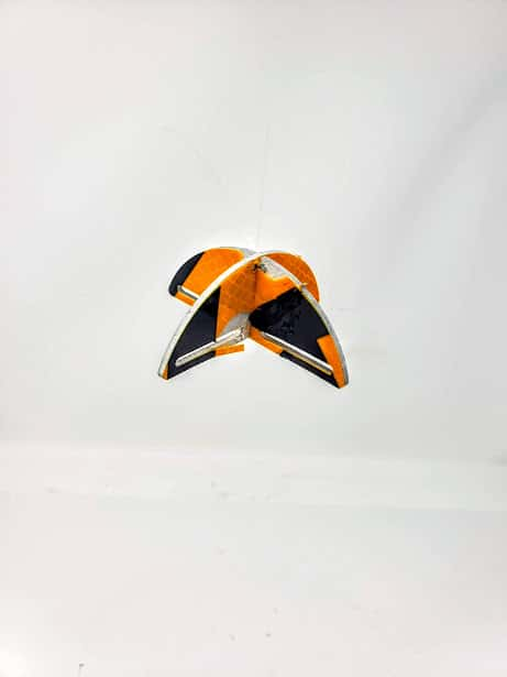
Our so-called “jellyfish” are the end effector and main visual component of the sculpture. Made from discarded street signs, the reflective 3d element teases the viewer's eyes as their tentacles wiggle around, made from the very cutouts that once resided within the pulleys.
Each jellyfish contains four discrete 2 mm diameter holes at the top, allowing for a stand of fishing line to be tied to it. The 3 mm slots at the bottom allow for visual intrigue, as well for the tentacles to attach with a piece of wire. These jellyfish have been, quite appropriately, cut with a waterjet in two parts, allowing for a precision cut with our unusual material. The cut was so precise, in fact, that we needed nothing other than friction to hold the two pieces together. Sexy! hehe
A sneaking strand of fishing line ties to discrete holes in the top of the jellyfish and rises to the pulleys above.
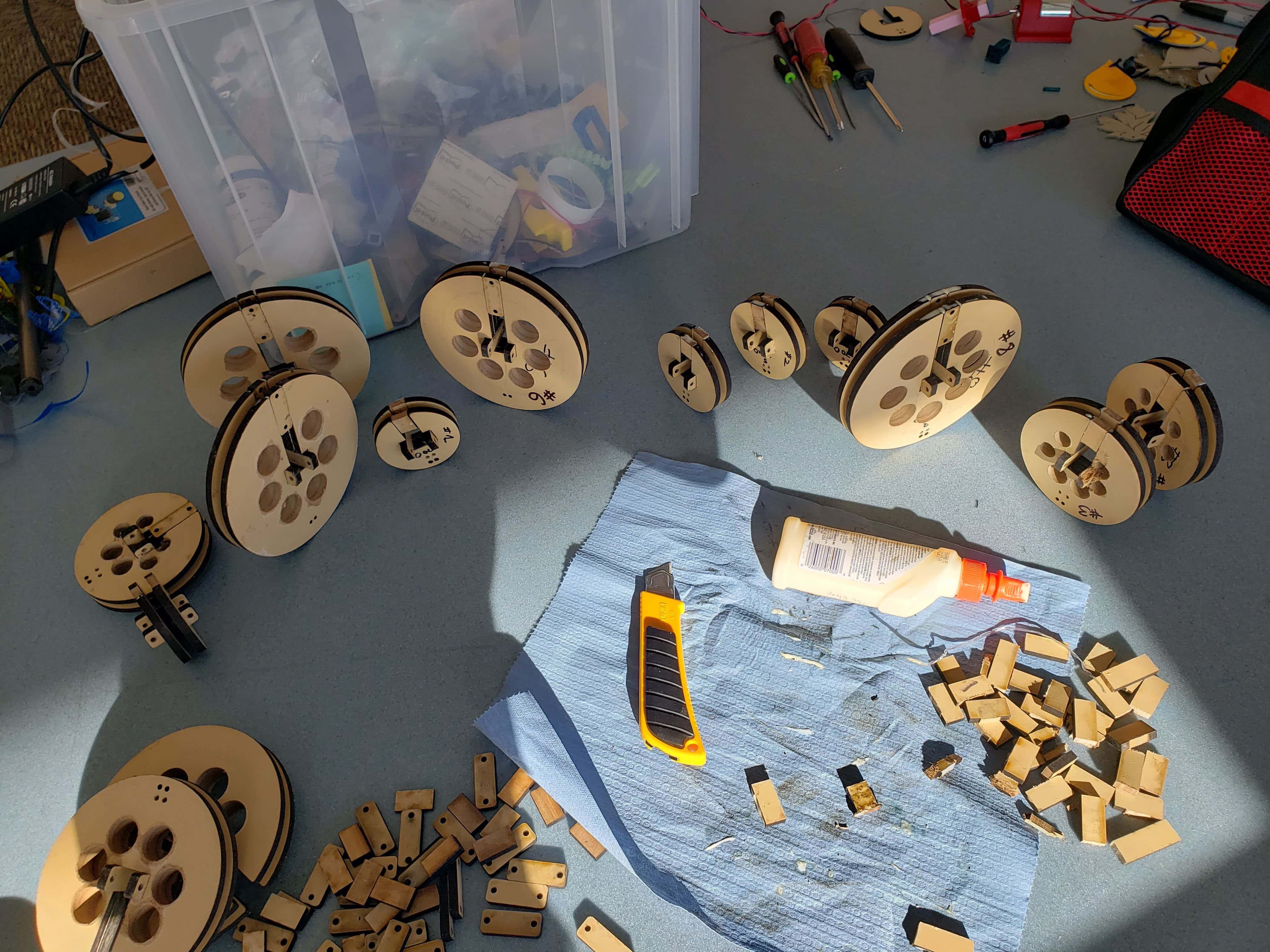
The Pulleys - The Driving Element
There are nine unique pulleys for each shaft. The radii of these pulleys were determined by our simulation software . After tuning the parameters in the simulation, we decided on a final shape and moved on to manufacturing 72 pulleys (a total of 216 circles to cut).
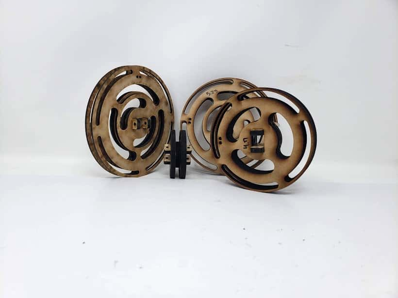
We cut our simple but effective pulleys out of what we believe to be a discarded cabinet. Each pulley is made of 3 laser cut circles and two tabs. (exploded view of one pulley). The inner circle is where the fishing line winds around, and the other two keep the line in place. The center hole in each pulley is rectangular, and slides onto our square shafts with space for two tabs. The tabs sit perpendicular to the circular face. Each tab has two holes, one on each side of the pulley. A 6-32 bolt and nut go through the tab and the shaft to hold each pulley in place. Additionally, there are many lightening holes in each pulley. Each pulley was assembled using one of our custom glueing jigs and wood glue.
The Shaft - It’s Pink!
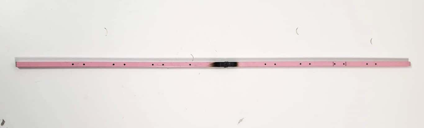
Deep in the metal waste bins in the Wellesley RDF, we found… square shafts! Polygonal shafts are great for power transfer as all torsional motion is transferred by the shape, leaving only lateral motion to constrain. In addition, the flat edges are easy to cut and attach to (no slippery circles!). Alas, our shafts were too short for the desired effect. Never fearful, we designed and milled center connectors, and then proceeded to weld two shafts to each connector. This created 8 longer shafts which we then cut to the same exact size. From here, we put holes corresponding to the tab location of each pulley to allow the bolts to pass through the shaft. Piece of (pink) cake.
Motor and Shaft Mount - Holding everybody up
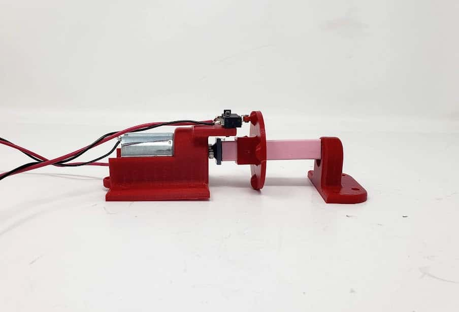
The next piece of the puzzle was mounting each shaft to the wooden frame. To do this, we designed mounts that are directly connected to the top cross beams. On one end, we have a mount that fixes the motor in place, as well as holds the limit switch (insert link). The other end has a mount that holds a bearing up such that the center of the motor shaft aligns with the center of the bearing. Each set of mounts are directly opposite each other on the frame and there are eight total sets, one for each shaft.
Shaft to Motor/Mount Interfaces - Did you forget about me?
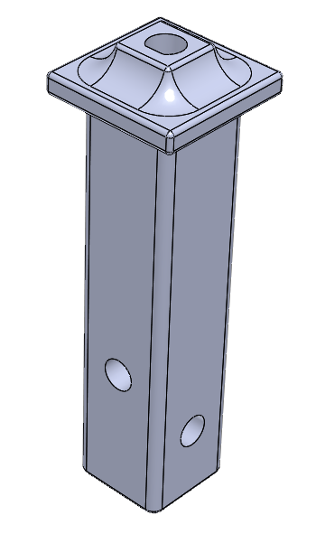
Now to connect the pink shaft to the mounts/motor… On the motor side, we connected the pink shaft to the motor shaft using a 3d printed interface. The motor shaft is keyed, again providing geometry for excellent torsional power transfer.
The interface to the pink shaft is square and is pressed and then screwed into the shaft. On the bearing side, we have a simple interface that is also pressed into the end of the pink shaft, and has a cylindrical extrusion that fits nicely into the bearing, reducing friction while keeping the shaft aligned.
Limit Switch DIY Encoder
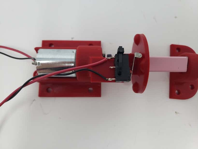
At the end of sprint 2, we realized we needed more sensor information than was originally planned. To solve this, we made a cam follower system with the limit switch and an additional 3D printed piece.