Overview
Our code is split into our software written in Python and our firmware written in C. In addition, we have a simulation for the sculpture dynamics written with p5.js.
Our project code can be found here.
Our website code can be found here.
Contents
Python
Our Python code handles all of our high level control, reading the input from the webcam and generating motor speeds for the Arduino. Broadly, it can be broken up into how we handle parsing the input and how we handle controlling the Arduino.
Person Detection
Algorithm Selection
For our person detection algorithm, we used SSD (Single Shot MultiBox Detector) with a Mobile Net backend. As we didn't have access to any kind of inference acceleration hardware, we had to pick an algorithm that was computationally efficient. To this end, we selected SSD + Mobilenet. SSD is an object detection algorithm that was designed with efficiency in mind, and computes all bounding box proposals on a single forward pass. And, Mobilenet is lightweight CNN architecture designed for mobile devices. Together, we get a fast, yet powerful algorithm that we manage to run at nearly 40 fps on a laptop cpu.
Implementation
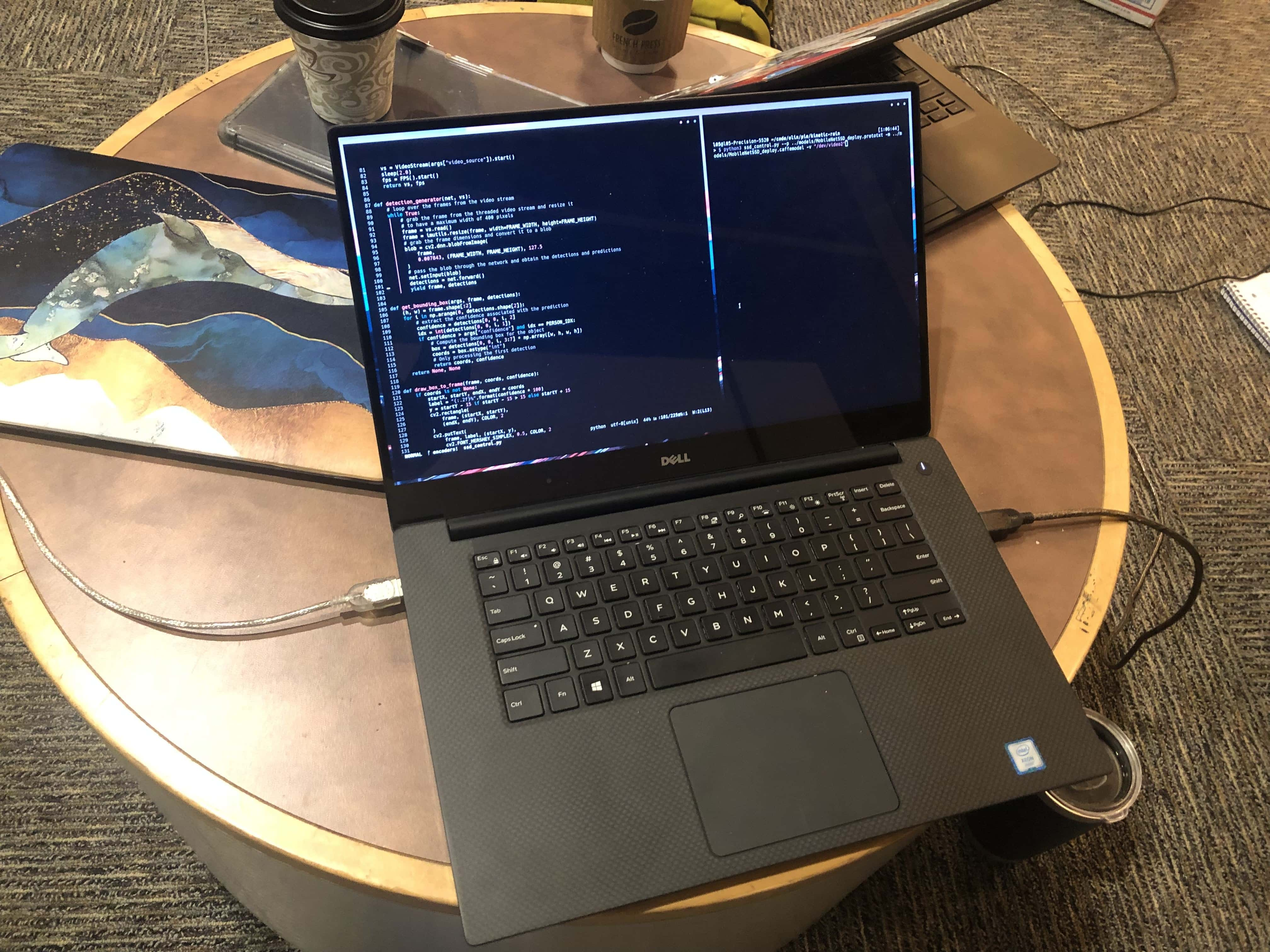
For implementation, we loaded our model into OpenCV and used the `dnn` module to run our forward pass. A single frame is processed over several steps:
- Pull image from video stream
- Resize image to 300 x 300
- Compute forward pass on image
- Extract first bounding box with `Person` label
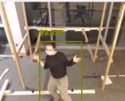
As we only care about the X position of the person as they walk across the frame, we reduce the bounding box into an average X value that we use to calculate motor speeds.
While the above process works for most cases, there are some edge cases - specifically when there is no person detected within the frame. Then, there are two possibilities:
- There is no one in the frame
- There is someone in the frame, but they were not detected
In the first case, we don't need to worry and can safety return the sculpture to a resting state. However, in the second case resetting would produce undesirable behavior - the model losing track of someone for a single frame would cause a jerking motion as the sculpture briefly tries to reset. To handle this, we simply save the last known location of the person we are tracking. If that location is near the center of the screen, we can safely assume that they are still somewhere within the frame and act as if they haven't moved. And, if they are near the edge of the frame, we can likely assume that they've left the frame and start resetting.
Control
Motor Calibration
Since we want the sculpture to respond as a person walks across the frame, we need to know where the motors are relative to the person. We only care about X position, so this is a straightforward calculation of subtracting each motor position from the person's position to obtain a difference. To determine the location of each motor within the frame, we have an interactive script that allows a user to click on each motor in the webcam feed. The script records the X-coordinate of each motor to a file, which is then read during the algorithm setup.
Motor Speed
Given the X position of the person within the frame by our CV model, we can calculate the appropriate speeds for the motors. It is important to note here that we are setting speeds, not positions, when controlling the motors. Generally, the closer a person is to a motor the faster is moves up, and the farther someone is to a motor the faster it moves down, stopping if it reaches the top or bottom. This property is what creates the wave like motion that we see when someone walks in front of the sculpture. To model this behavior, we designed a specific function which becomes more negative the further you move from 0. This function then takes in the normalized distance between the person and the motor we are calculating the speed for. If the person is close, the motor is driven up, and if they are far, the motor is driven down. The output of the function, bounded between 1 and -1, is then scaled to an appropriate motor speed, bundled into a list with every other motor speed, and sent to the Arduino.
Dependencies:
C
Our C code handles all of our low level control, reading motor speeds from a serial input and driving the actual components. The primary concerns here were parsing the input over serial and controlling the motors.
Serial
Early on in the project we used relatively naive serial processing and ran into issues with corrupted serial data. Specifically, we were trying to read all bytes for a message on a single loop but were running into issues when it wasn't all ready. To ensure that we had reliable communication, we updated our processing to handle input over several loops. This involved updating our protocol to include start and end tokens. Now, the process involved multiple pieces:
- Read bytes from serial, discarding until we find a start token
- Once we find a start token, read bytes and save to a buffer until we find an end token
- Once we find an end token, set flag for full message read and return to step 1
with this processing in place, we ensured that we always had a full message to parse when we read our buffer. To parse the buffer, we simply split on commas using strtok, then process the integer motor speed using atoi.
Control
Control for the motor is kept relatively simple by the fact that all we have to do is set motor speed and direction. However, there are some complexities in controlling many motors that have varying states and in using our DIY encoders. To handle the many motors, we define a simple `struct` that maintains all state for a single motor, like speed, direction, last direction, etc. Each motor is then processed in isolation using only the new speed designated by the serial message and the previous state of the motor.
Handing the DIY encoders is more complicated. In essence, they are just limit switches that are hit every 90 degrees of rotation. So, the baseline handling is simple - if the switch associated with a motor reads high, increment or decrement the position by 90 based on the direction the motor was running. However, there are a few edge cases we also have to handle:
- The case where we switch direction while a switch is pressed
- The case where momentum carries us over a switch
In the first scenario, our naive code breaks because we read the switch as being pressed, but we never hit it a second time coming back resulting in us missing 90 degrees. To handle this, we save the direction we are moving when a switch goes high. Then, if the motor is moving in a different direction when that switch goes low the next time, we know that we have hit this edge case and can handle it manually.
In the second scenario, our naive code breaks because we think we are moving one direction, but are in reality being pushed the other direction by momentum resulting in incorrect encoder readings. To solve this, we ensure that we only change direction when a switch is low. This means that momentum would have to carry the axle a full 90 degrees to hit another switch. As this is unlikely given our hardware, in practice this (imperfectly) handles the problem.
Processing
The simulation we did in the first sprint was written using the framework p5.js on OpenProcessing. It primarily leverages p5's webgl backend to render the scene in 3D, and p5's DOM access to create menus for manipulating system parameters. The actual dynamics governing the simulation are relatively simple. The entire system is made up by a number of axles, each of which holds a number of voxels. Each voxel has a simulated pulley radius, allowing us to calculate the height of the voxel given the angular position of the axle it is attached to. Separate from the sculpture, a simulated human walks across the scene. Then, rotational speeds are passed to each axel following the procedure outline in the Python section, allowing us to simulate the interaction with the sculpture.
The sculpture is also produced to scale for ease of use when creating our final design. This is specifically useful for the pulley radii. They are unchangable once cut for the physical sculpture, and also perform the critical role of deciding the shape that each axel makes when rolled up. As a result, extra functionality was added to modulate the sizes of the pulleys to make manufacturing easier, and an option to export all pulley radii was used when manufacturing started.