A walkthrough of all the individual components of our system, and how they work together to create SaniBot
The chassis was created out of plywood by using the ShopBot to carve out spots for the wheels and electronics. An inch thick piece of cardboard was used in order to make the chassis more durable and able to carry more load as it has to withstand bumping into walls and carrying a large mount for the hand sanitizer dispenser. There were holes in the chassis carved out in the chassis for mounting the wheels and allowing wires to pass through from the Arduino to the motors. The wheels were mounted by drilling holes into the chassis and using a bracket that has holes to mount to the motor as well as threaded holes to place screws into.
Just drop the blocks into the page, edit content inline and publish - no technical skills required.
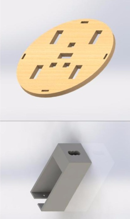
The hand sanitizer dispenser we acquired was found on Amazon. In order to mount it to the chassis of Sanibot, we created a hole in the chassis where two piece of plywood were screwed in using wood screws. Then a longer piece of wood was screwed into the two smaller pieces of plywood in order to allow the mount for the hand sanitizer dispenser to have some additional height and a stronger base. Then, the hand sanitizer dispenser was attached to this longer piece of wood using metal hooks.
The cover of our chassis was created by wrapping a thick sheet of plastic around the base of the chassis. The sheet was earlier colored with paint. Then, a plate was laser cut using acrylic. The plate had a hole for the hand sanitizer dispenser mount. The plate was glued on top of the plastic base attached to the chassis.
This type of switch was used to detect when the robot bumps into an obstacle, like a wall. If the switch is pressed - when the robot collides with something - then the robot should either stop, reverse, turn, and keep moving, or stop and move forward, depending on if a front or back switch is hit.
We wanted our robot to be as portable as possible, and in order to do that, we needed to move from a wall power supply to a battery pack. We had two battery packs arrached to our robot - one to power the motors, and one directly to the Arduino, since 12V wasn't enough to power four wheels and the Arduino.
This distance sensor was used to stop the motion of the robot, once it detects a hand. The IR sensor outputs analog values depending on the distance from the object detected. A threshold value from these outputs was then used to stop the robot in code.
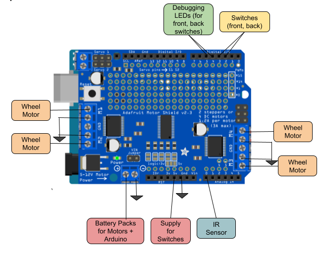
Our robot had a drivebase with four wheels, so we had to power and ground each of the wheels to a different pin on the motor shield. The combination of the motors and the tactile switches were too much for one breadboard to have enough pins for, so we added a second breadboard to the system, and connected the both
In order to allow our switches to work as intended, we incorporated a debouncing technique, which works as follows:
We begin by setting a debounce delay constant, in this case, 50 milliseconds. Then, we check if the tactile switch has been pressed. If the reading of the switch has changed since the last reading, reset the debounce timer (measures the time since the switch change was detected). When the debounce timer exceeds the debounce delay constant, if the reading of the switch has not changed since the timer began, we set the last reading variable to this reading. Otherwise, we assume that the reading was caused due to noise and we ignore it.
Our robot has the capability to move in a straight line until an IR sensor connected to it is triggered. The way this trigger works is that first, a threshold value is set. If the threshold value changes (i.e. if a hand is waved over the IR sensor), the robot will stop for 10 seconds - enough time for the person who stopped it to grab their sanitizer
Our robot is set to automatically move forward when powered on. There are tactile switches fastened around the perimeter of the chassis, and the robot has been programmed to reroute itself based on the switch that was triggered.