Electrical Subsystem
Electrical Design
An overview of key electrical design decisions we made.
Computers
For the electrical design, we decided to use LiPo batteries and a Raspberry Pi to communicate over wifi with a laptop in order to create an untethered robot. To control the motors and servos, we used Arduinos rather than the Pi because we were more familiar with that setup, and started out with two Arduino Unos because one Uno did not have enough PWM pins for all of our motors and servos. When our Arduino Mega arrived during Sprint 3, we found that it was having communication problems with the Pi. After trying to debug for hours, we didn’t think we would be able to get it working and went back to using the Unos as they were already a functional solution.
Motor Drivers
We also had some trouble with our motor controllers and ended up trying out three different ones to find one that worked. We first tried Amazon RC Car Motor Controllers rated for up to 40A, but could not find a manual anywhere on the internet. After unsuccessfully trying to induce a response by sending signals over PWM at different frequencies and duty cycles, we gave up and borrowed an L298N Motor Driver. The L298 had a manual and tutorials and we were able to successfully operate it, but the problem was that it was heating up due to having only a 2A peak output current which was too low for even a single one of our motors. At that point, we researched high-current rated motor drivers with good supporting documentation at a low price point and found the BTS7960 High Power Motor Driver Module which came with arduino example code and was rated up to 43A. This experience taught us a lot about how to use motor drivers and what factors are important to take into account when choosing one.
RGB LED Strips
After adding LEDs, it seemed that the wifi signal from the pi would stop working at random times including while the robot was driving, and continue driving until it hits something. We think this was because the Pi is sensitive to power changes. We added a second portable power bank rated for 5V and 2A to power the pi which fixed the issue.
Layout
In terms of the physical layout of the electronics on the robot, we made several decisions which contributed to overall success. Firstly, we stacked the breadboard for power distribution on top of the battery since we wanted the battery to be in the center for weight distribution and the breadboard to be in the center to reduce wire lengths. To make this stacked configuration work, we put together a quick battery box which held the battery and allowed it to be swapped out easily. We bolted down the battery box as well as many of the other electrical components to prevent them from falling off since we tended to flip the robot over often for both storage and testing purposes. This layout also helped keep our electronics compact in the center of the robot.
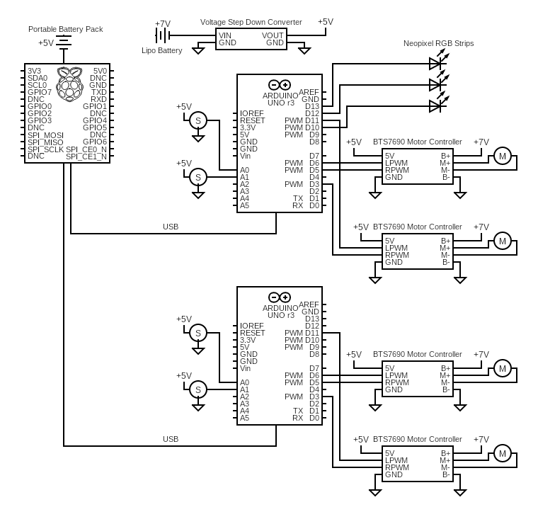
Circuit Diagram
Please to the following schematic for details of our electrical wiring:
