Mechanical Subsystem
Mechanical Design
Swerve Module
Normally, swerve modules use two motors mounted on top, and using gears, they transfer the ability to pivot and spin dnow to the wheel. This has the advantage of pivoting without limitation to the range or reaching a maximum angle. Unfortunately, these modules are very expensive and would alone put us outside of our budget.
Due to limitations in budget and performance of 3D-printed parts, we decided to form our own iteration of a swerve drive module that fits our needs. It uses a servo on one side of the platform to rotate the module and a drive motor that’s on the module for spinning the wheel that uses gears to convert the rotation from the motor to the wheel axle. The module assembly connects to the servo by an aluminum shaft.
In order to make the swerve module durable and easily maintainable, we made several key design decisions. We avoided using any 3D printed gears because they have low durability and high friction. Instead, we used aluminum pulleys with belts and shafts to transfer motion. We also 3D printed our own wheel hubs to have a larger contact area to the axle and more stability for the wheel. Additionally, for ease of changes and replacements to parts, all attachments to shafts are done using 3D printed clamps.
Connecting the Modules to the Platform
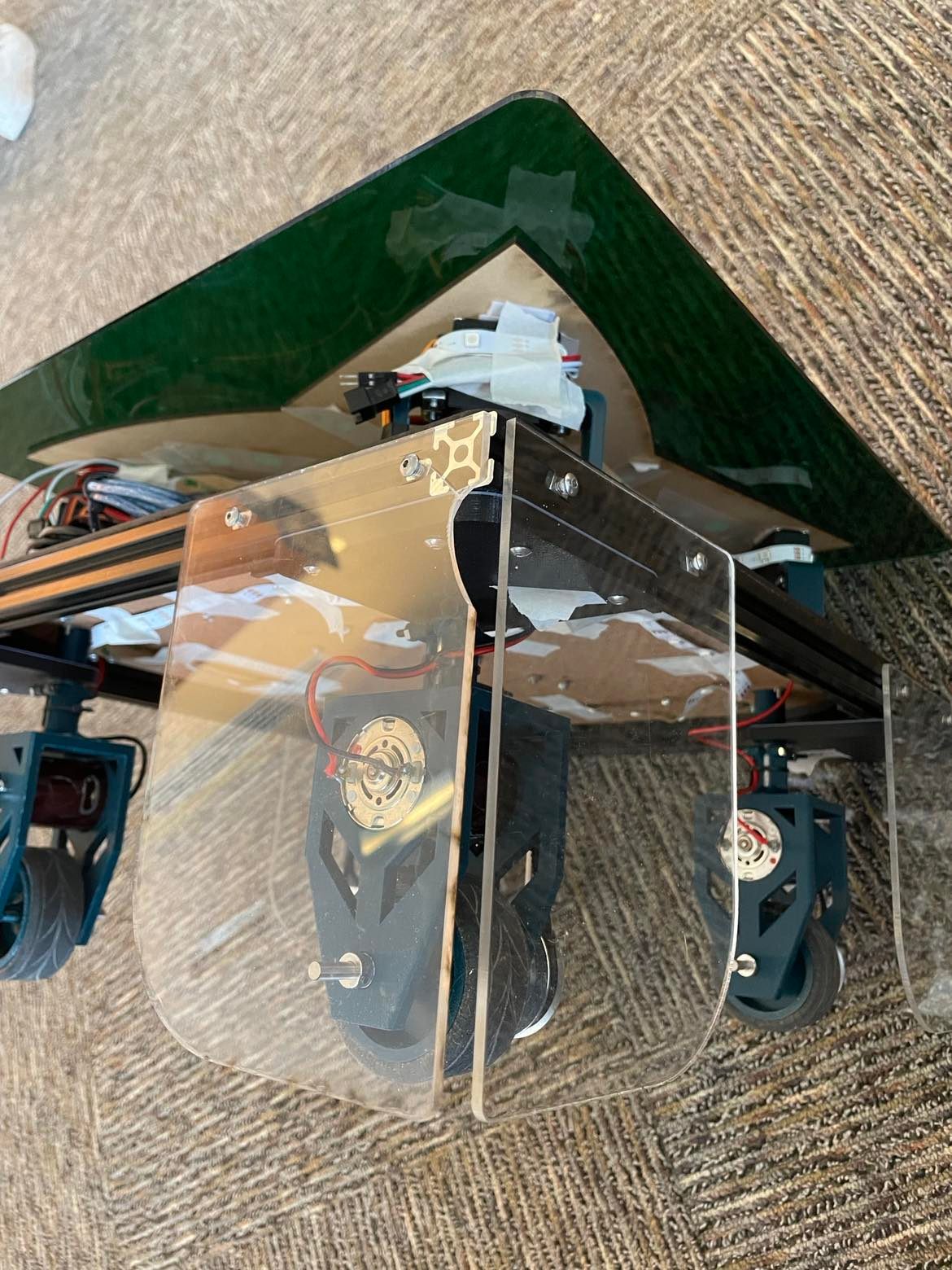
We decided to use a T-slot extrusion frame as a base to our platform for its stability and modularity. To prevent any unnecessary tension on the servo head, we mounted the servo on one side of the platform with 3D printed brackets and restrained the shaft through a 3D-printed bushing. For stability, we ensured that the bushing has two points of constraint: the main platform and a secondary mini-platform. We added shields to the edges of the platform to prevent damage to the swerve modules in case of a collision. The wires leading to the drive motors were also restrained with zip ties to prevent damage to solder points.
Full Assembly
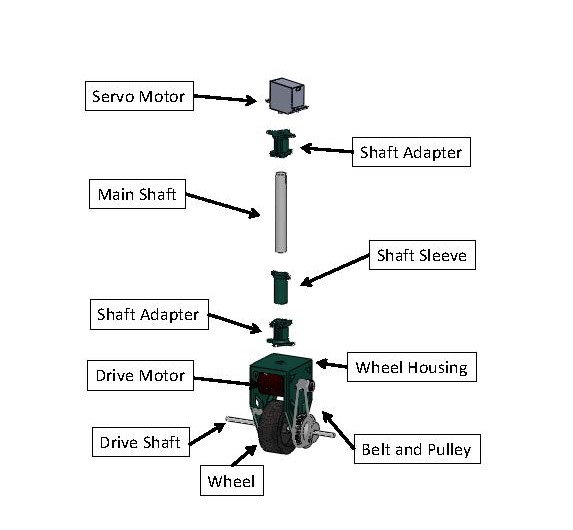
Swerve Module breakdown

An exploded view of a full module is shown above. A full module is all of the parts necessary to drive each wheel. At the top, we have the servo motor, which controls rotation about the vertical axis. It contains an attachment piece that adapts to the servo motor shaft. We drilled into the outermost holes to increase the diameter in order to fit the smallest size screws we had access to in the shop. This is how we mounted the servo motor to the shaft adapter. The shaft adapters are mounted onto the main shaft, tightened down via a screw and nut. The shaft goes through the shaft sleeve, which fits perfectly long inside the main platform, and supports the main shaft as a fixed hinge, further stabilizing the module. The lower shaft adapter is secured onto the wheel housing by epoxy, which is very strong and will not easily come off. The wheel housing contains the necessary components for driving the robot, including the drive motor, drive shaft, wheel, belt and pulley.
Multiple iterations of this design were created to account for unforeseen issues. Due to the high torques caused by the wheels and experienced by the shaft adapters, we redesigned the shaft adapters to be stronger and better able to withstand these forces. Additionally, before switching to epoxy we were using superglue to attach the shaft adapter to the wheel housing. However, superglue wore off and the shaft adapter ripped off. We decided to reinforce our design by using a combined method of epoxy and heat set insert, which we attempted and tested by using a mini torch to heat up a metal pin and inserting it through the shaft adapter hole and into the wheel housing. We quickly learned that epoxy does not melt, but this did not inhibit our design since the epoxy was found to be more than strong enough to support the driving forces.

In addition, to further protect our robot, we decided to add transparent bumpers to protect the modules from external forces/ contact. We decided to implement this considering how fast our robot drives and because we accidentally ran over a small object in testing and this broke our shaft adapter. This made us consider new design decisions that not only strengthen our robot but also protect it from experiencing any unnecessary loads when possible. Even with the bumpers implemented, the robot was still accidentally crashed into a corner and the corner of the bumpers broke. This validated our decision since we were prepared for this load on the robot by allowing the bumpers to absorb the force of impact rather than the modules, which would have likely broken in place of the bumpers in their absence.
Individual Components
Shaft Adapters
This shaft adapter concept is used to clamp to the trans-platform aluminum shaft to transfer torque from the servos to the wheel assembly. The same piece can connect to the servo horn using the holes at the base of the part via a screw and nut, and it is glued with epoxy to the wheel housing and all the respective parts. Originally, the design on the left was used, however, we noticed multiple flaws with it. First, the screw mounts at the top were too thin and they collapsed under the force from the screws while being tightened to the shaft. Second, the walls for the mount were too thin so they broke easily. To remedy the second issue, we made the walls thicker and changed the 3D print orientation such that the print lines are along the length of the shaft, using the “grain” of the 3D printer in our favor for strengthening the part.
Platform Shaft Sleeve
The sleeve acts as a bushing to constrain the motion of the shaft to one axis of rotation. There is enough clearance to minimize friction, but still maintain enough constraint. It acts as a fixed hinge and serves as another point of contact while also stabilizing each module, keeping it as vertical as possible (shaft should be perpendicular to the ground).
Wheel Housing
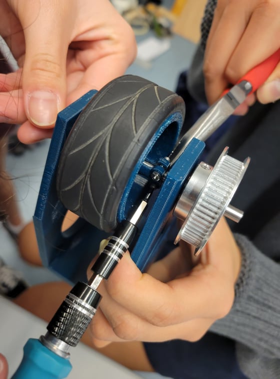
This is the main housing for the swerve module. It holds the drive motor, pulleys, and the wheels. Originally, the frame was wider and longer, but we found that the extra size took additional time to print, did not add much advantage, and had a concerning small clearance between the bottom of it and the ground. We also went through multiple iterations with the design to allow for better integration with the motor and the gears that connected the wheel and the motor to get optimal tension in the pulley and that all parts were properly supported. We wanted to make sure that the part did not take too long to print, so we added aesthetically pleasing cutouts to serve a dual purpose.
Wheel
The wheel was designed to fit the wheel rubber traction
material we adopted from the PIE scrap bin. We decided to 3D
print the wheels such that we could increase the diameter and
make it stronger to decrease the contact patch with the ground
and reduce friction in the tires. We also designed the wheels
to have mounts for each side built into the design to help
stabilize the wheel and keep it vertical. We did encounter
some spacing issues with our wheels in the wheel housing since
the wheels with the mounts were wide enough to take up the
majority of the available shaft space in the housing, so it
was difficult to access the screws to tighten the wheel down.
We purchased collars that fit around the drive shaft since we
needed to constrain the position of the shaft via a fixed
hinge in the horizontal direction. We also implemented
bearings to reduce the load on the shaft and spacers to reduce
friction between the tire and the housing wall.

Servo Mount
We used the platform shaft sleeve to constrain horizontal motion of the swerve drive module, but decided against constraining vertical motion from the assumption that the servo can handle that amount of force pushing into the gearbox. To achieve this design, we made the servo mount to hold the servo a certain distance from the platform such that there is only a little clearance between the shaft adapter and the platform shaft sleeve. As a result of the four servos holding up the weight of the robot, we do not have to deal with much friction between any of our custom parts.
Mini Platform
After discussing an earlier iteration of the swerve-bot with the professors, they suggested we add a second point of contact to support the “platform shaft sleeve.” At the time, we only had the top of it mounted to the platform using screws. Since the job of the platform shaft sleeve was to minimize any horizontal motion in the swerve module, and it was going to have a lot of stress, we decided that a good solution to add a second point of contact would be a mini platform. This platform goes on the underside of the frame and the platform shaft sleeve fits snugly into the large hole. This was successful in preventing excess stress on the main point of attachment.
Frame Bracket
Using T-slot extrusion rails made it very convenient to form the frame and attach objects to it. We decided on a square design for the frame, using the inner sides to mount the brackets. We used this design that had two points of contact on each side for increased stability in addition to the large filet for stiffness of the frame.
Shaft Collar
The inner diameter of both pulleys in a set is 5mm. This is perfect for the steel rod used to transfer energy to the wheel, however, the drive motor shaft diameter is significantly smaller, a larger tolerance than expected. This caused the pulley to be positioned off-center and resulted in the whole assembly vibrating intensely. Our solution to this was to 3D print a sleeve that goes around the motor shaft, extending its outer diameter to just under 5mm. This resolved the vibration issue.
Top Plate
The top plate was designed to give the project an interesting visual when the robot is spinning. We laser cut a piece of MDF with the main design, a sheet of acrylic and used epoxy we used for other parts to adhere these to one another. The entire cover attaches to the four servos with velcro for easy detachment when we are adjusting the electronics. In order to really showcase the pattern, we added LED strips underneath to shine through.