Electrical Subsystem
An overview of our electrical subsystem.
Electrical Components
- Arduino Uno
- CNC Motor Shield
- A4988 Motor Driver x 3
- NEMA 17 Stepper Motors x 3
Schematic
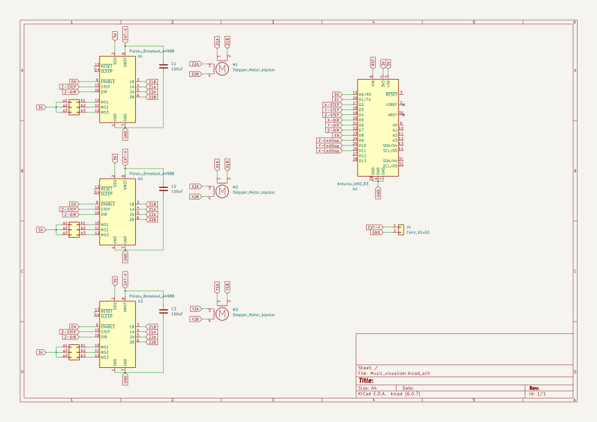
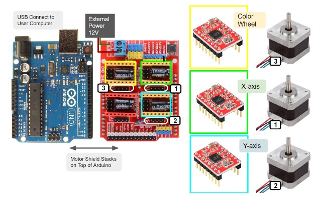
The main electrical components include an Arduino Uno, a CNC motor shield, three A4988 motor drivers, and three NEMA 17 stepper motors. The whole electrical system is powered by a 12V external power. The Arduino board, which has Grbl installed, controls the motor movements upon receiving command from the user’s laptop via the serial port. The three stepper motors control the X and Y axis of the gantry and the color wheel separately. The potentiometer on each of the A4988 drivers is adjusted such that the current the motors operate on is about 80% of the maximum current.
Firmware Design
Grbl v1.1 is installed on the Arduino, which is connected to the user’s computer with a USB cable. For testing purposes, we used Universal Gcode Sender (UGS) as the GUI for streaming G-code and controlling motor movements. This helped us to eliminate software defects as a potential cause to any unexpected motor movement. Later, we created a python script that integrates functions for generating G-code based on coordinates of spirograph points and streaming G-code to Grbl on the Arduino.
Reflection
There are many improvements that can be made to the current electrical system. We could add limit switches to each end of the two axes of the gantry, which would act as both an origin of the homing routine, and an emergency switch in case the pen is moving off the canvas and getting stuck. Additionally, we could use a battery instead of a power adapter to reduce the difficulties in wire management. There could also be a power switch added to the whole system, so that the user can turn it on and off easily.