Process
An overview of our development cycle and timeline.
Sprint 1
For our first sprint we wanted to test out a drawing mechanism. No one on our team had experience with gantries so we wanted to learn about them first in order to decide the scope of our project. We made a vertical X-Y gantry in less than two weeks that used servo motors and weight to center the pen holder in the middle. We found after our sprint that the design worked well but only for one color and we felt that in order to fully visualize music, we need multiple. A multiple color mechanism would be difficult with a vertical gantry system because of gravity so we decided to shift to a horizontal X-Y gantry like those found in 3d printers. We also found that our initial design was pretty quick and we wanted more of a challenge. Our software/electrical team found that calibrating the motors took more time than expected and knew that it needed more attention in the future.
Mechanical
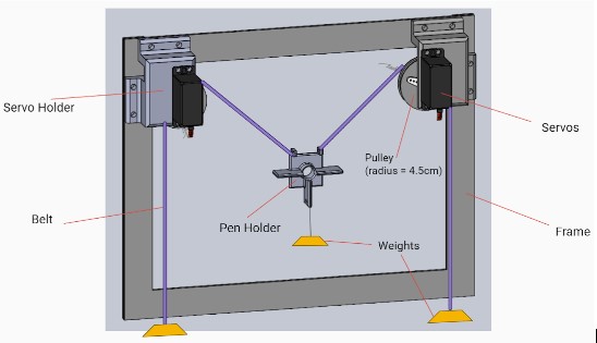
This sprint provided a good proof of concept and gave the mechanical team a nice challenge to warm up with. During this sprint, we researched different kinds of gantries and chose the vertical gantry because of its relative simplicity, it only required two motors and gravity. We used a combination of sketch modeling techniques and rapid prototyping to quickly manufacture a cardboard frame with 3D printed motor mounts, pen holder, and pulleys. Testing this system revealed some of the challenges we might need to think about when designing a gantry. These included friction and slippage on the pulleys, the importance of keeping parts linear and rigid, as well as considerations of required torque to overcome the forces of gravity and friction caused by the drawing mechanism.
Electrical
Since the stepper motors purchased did not come in time, we used servo motors instead in the vertical gantry. The main problem with these motors was that they did not have enough torque to pull the belt which has the pen and weights attached to. But they worked well for concept proving in this sprint. To drive these two motors, an Arduino board was sufficient, therefore we did not include any other motor shield. The arduino is connected to the user's laptop via a USB port.
Software
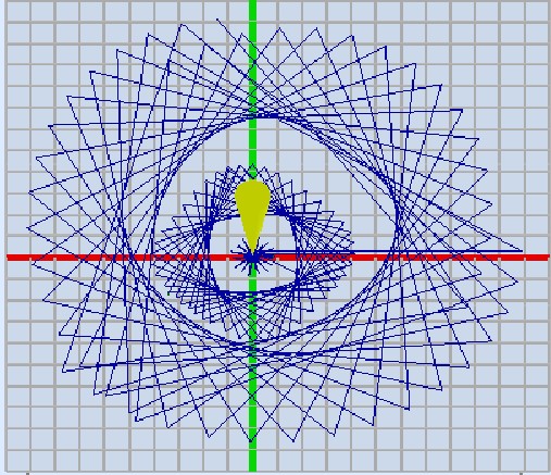
For Sprint 1, software focused on writing scripts to control the servos in order to draw different shapes with out gantry. We discovered that while the code worked for the servos when they were not integrated, upon integration the pulleys would slip off the servos, which meant we were not able to test if the shapes were drawn correctly.
Since we decided to pivot towards a horizontal gantry system, we turned our attention towards figuring out how we wanted to process the audio data. As we brainstormed potential methods, we focused on having a simple circuit with LEDs that lit up when audio input was detected.
At the end of this sprint, we decided that our next priority was to have the drawing commands be different depending on audio input -- essentially integrating our audio processing with gantry control. However, we knew this would be a significant change as we would also be dealing with a different gantry system and different motors.
Sprint 2
In sprint 2 we made a lot of progress. We fully shifted to a horizontal X-Y gantry and were able to achieve a working gantry in two weeks. We had to order a lot of our parts this sprint like V-slot rails, wheels, stepper motors, belts, and pulleys. For the software side, we translated Cartesian coordinates to motor motion and began working on the spiral art design. From this sprint, we decided to stick with the mechanical design but to work on reducing friction and adding stability. We decided that we needed a CNC motor shield which is better suited to X-Y gantry systems.
Mechanical
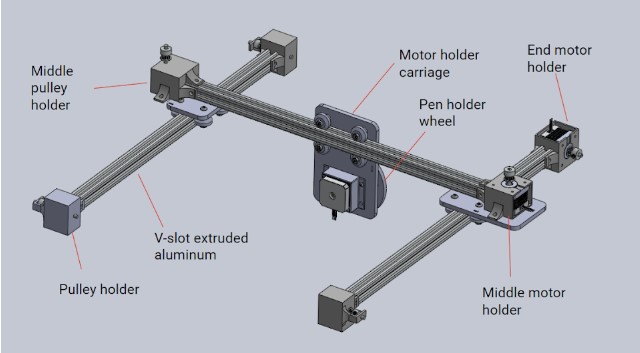
During this sprint, we learned some of the basics of creating a gantry with extruded aluminum. For example, we learned the difference between T-slot and V-slot. For our purposes, because we wanted a v-wheel carriage that rolled smoothly on our gantry, we decided to use V-slot aluminum. The rails are also anodized to a nice black color, which looks sleek. In this sprint we implemented two out of three stepper motors, both mounted on one side of the gantry. These were Nema 17 steppers with a torque of 20 N-cm. After an integrated test, however, we found that these motors couldn't quite drive the gantry with the required speed and precision. The test drive of this system was successful but super slow! We also noticed that the timing belts did not have enough room and were rubbing against the wheels.
Electrical
After switching to Nema 17 stepper motors, we used an Adafruit motor shield which is stacked on top of the arduino board. The two main challenges were: 1) Moving motors in both the x and y axis synchronously requires a fast and robust algorithm; 2) Serial communication between Python and Arduino IDE was slow and unreliable. To tackle the first challenge, we take the coordinate of a point, and loop through a function that moves x and y in tiny steps repeatedly, such that the “zigzag” movement is subtle enough to be negligible. We learned by the end of this sprint that most CNC machines use Gcode and CNC motor shield to enable such movement. Therefore, we decided to switch from Adafruit motor shield to CNC motor shield with the hope of avoiding using Arduino IDE.
Software
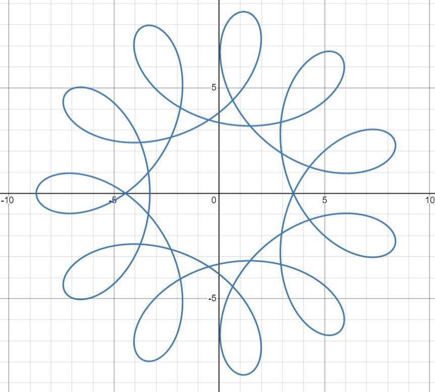
For sprint 2, the software team decided that to visualize music using spirographs. Consequently, we dedicated time to understanding the formulae that produce spirographs and translating the formulae into functions that return positions. Software modified these formulae by having the parameters be determined by the most salient frequencies in the fourier transform of the audio signal. A deeper explanation of these formulae can be found on the Software page.
Additionally, software also figure out simple motor control commands through Arduino. However, we ultimately decided to switch to using the CNC shield to simplify the simultaneous movement of multiple motors.
Sprint 3
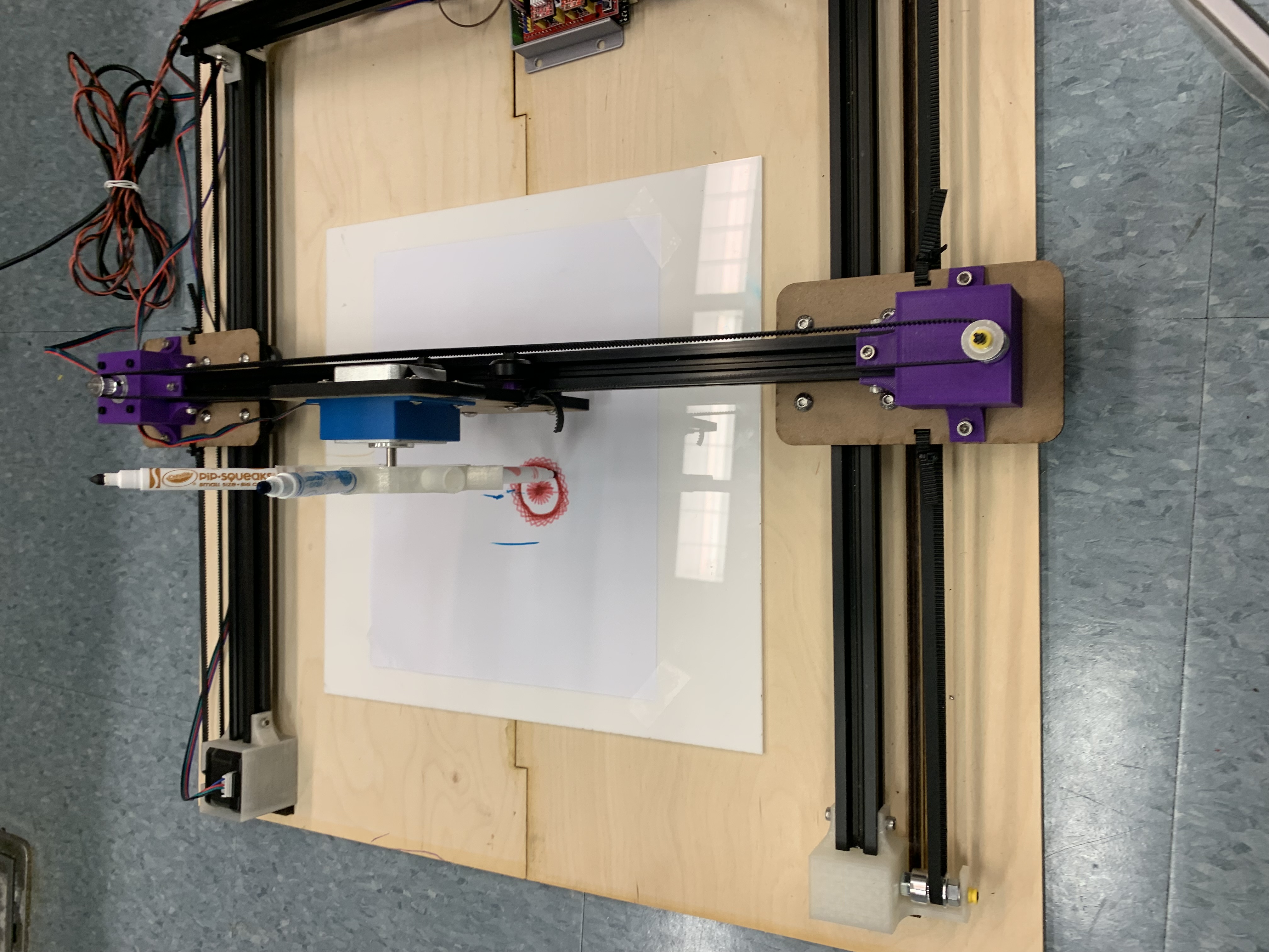
Our last sprint mainly focused on the spiral art algorithm and converting the position to Gcode commands. We also built a user interface where the user can pick a song. On the mechanical side, we added a base, acrylic board, and the color changing mechanism. We worked a lot as a whole team on integrating and testing small problems during this sprint and after.
Mechanical
The main issues we aimed to address in sprint 3 were reducing friction in the gantry, particularly in the y-direction as the motor was having a hard time moving the entire x-axis bar across the frame while being driven from just one side. We made a number of minor edits to give it a helping hand, including moving the timing belts slightly away from the wheels. We also mounted the gantry to a wooden base to keep everything at right angles. Both of these significantly improved the performance. Unfortunately, one of our motors stopped working, likely due to burnout. At this point, we decided to shift to a stronger, 42 N-cm stepper motor. Another feature we worked on was the holder for the pens, which was originally made from a disc of laser cut material. We found that this design was a bit wobbly so we designed a 3D printed pen wheel instead.
Electrical
After talking to many groups that have experience with using CNC motor shields, we decided to use GRBL as the firmware for faster testing and debugging process. Once we had GRBL installed on the arduino board, we were able to use Universal Gcode Sender (UGS) for basic motor movement. Then with UGS, we calibrate the XY axis motors. Next, we wrote a Python script for generating and streaming G code commands to the CNC motor shield. The main frustration with this is the slowness of serial communication between python and GRBL, and the motor movements, which leads to a very long drawing time.
Software
For sprint 3, the software team divided their efforts between integrating with the new CNC shield and developing a user interface.
To integrate with the CNC shield, the software team decided to use GCode and GRBL. Software learned how to create and write to GCode files, as well as which GCode commands were the most pertinent for the project. Additionally, software also learned how to stream the GCode files to the CNC shield for motor movement. A deeper explanation of this process can be found on the Software page.
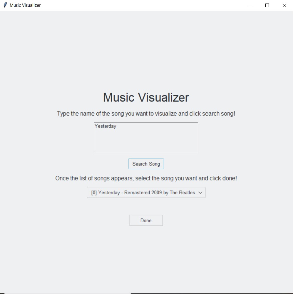
For the interface component of the project, the software team chose to use Python and tkinter in order to develop a simple in which the user could enter a song for visualization. Whilst developing the interface, the software team decided to switch from the fourier transforms used in sprint 2 to using the Spotify API for the audio data. A deeper explanation of this process can be found on the Software page.
Final Deliverable
Our final tasks included adding multiple concentric spirals and implementing a color changing mechanism from a software perspective.
Mechanical
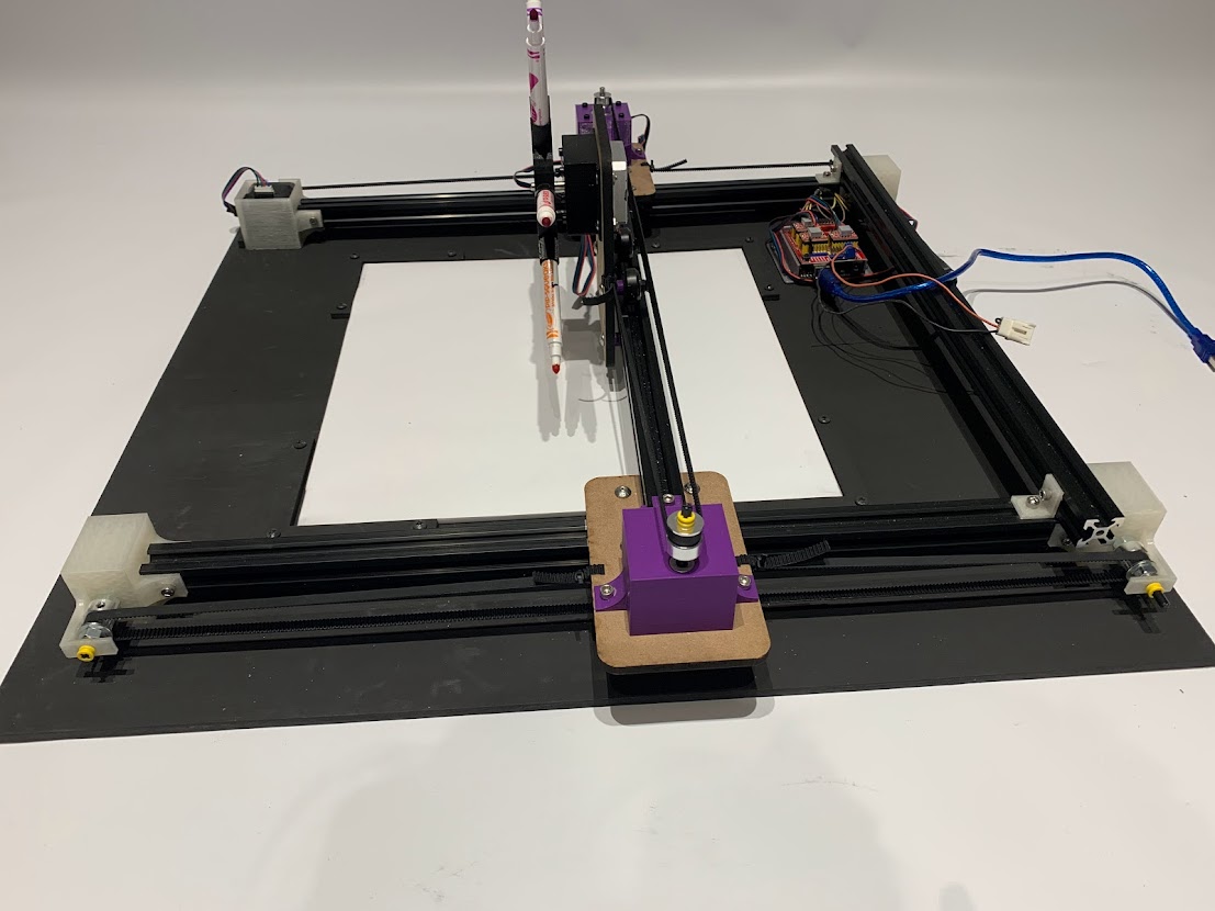
During our last week leading up to demo day, the mechanical team focused on tidying up the design and making minor changes to make the gantry draw as smoothly and precisely as possible. We created a frame to hold the acrylic canvas in place and painted everything black. We also reprinted the holder for the pen wheel motor so that the motor could be screwed in place.
Electrical
After deciding not to install limit switches for a homing routine, we focused on the stretch goal – color wheel turning. We calibrated this motor differently so that one step in the command represents the steps needed to turn from one marker to the adjacent one. The potential problem with this is that we always have to make sure the initial position of the wheel has one marker pointing vertically downwards, otherwise the turning command would not work. We also did a quick clean up of the wires by taping them around the canvas frame. In the future, this could be done with better tools such as wire carriers and drag chains that are specifically used for CNC machines.
Software
The first task the software team tackled was the ability to have multiple concentric spirographs. The problems we had in previous sprints with secondary spirographs appearing in incorrect locations was resolved by having all of the spiral positions be dependent on previous spirals. To test if the spirals were generated correctly before moving the gantry, we used Universal GCode Server, which produced images such as to the right. To implement the color changing mechanism, we modified how we calibrated the motor responsible for the color wheel, which enabled easy transition between colors.