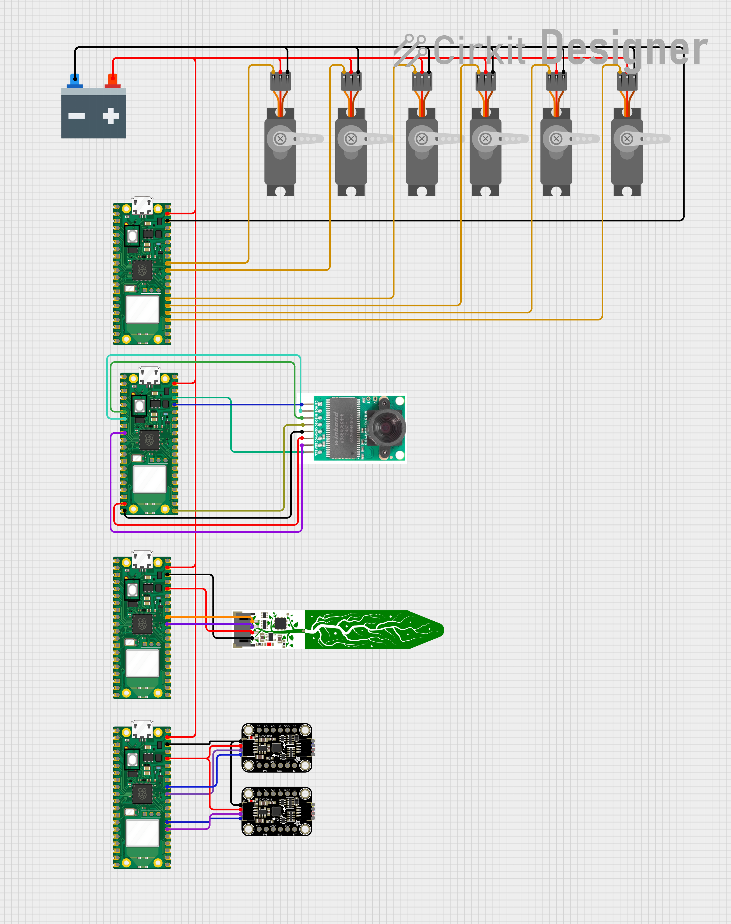
Circuit Diagram

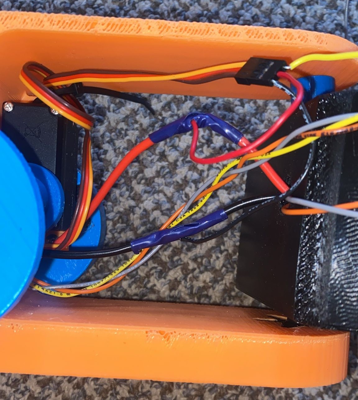
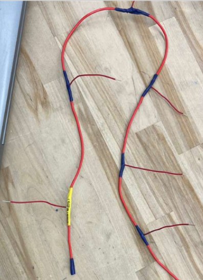
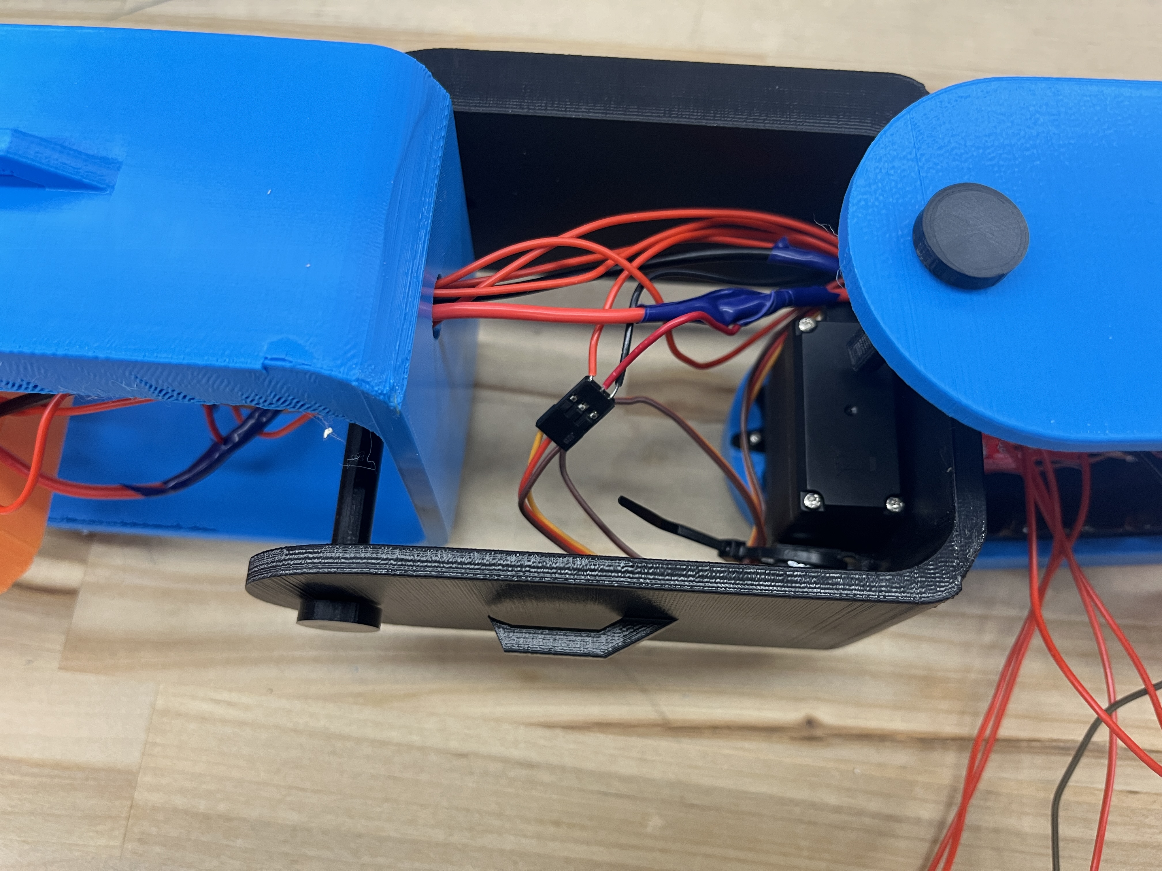
Electrical components that powered the snakes motion, soil sensor, camera, and location tracking.

Core Components

Core goals behind each design decision we made.
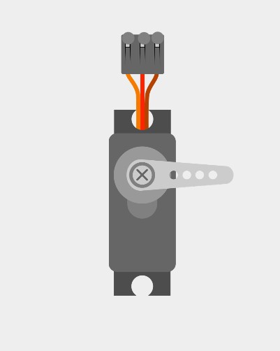
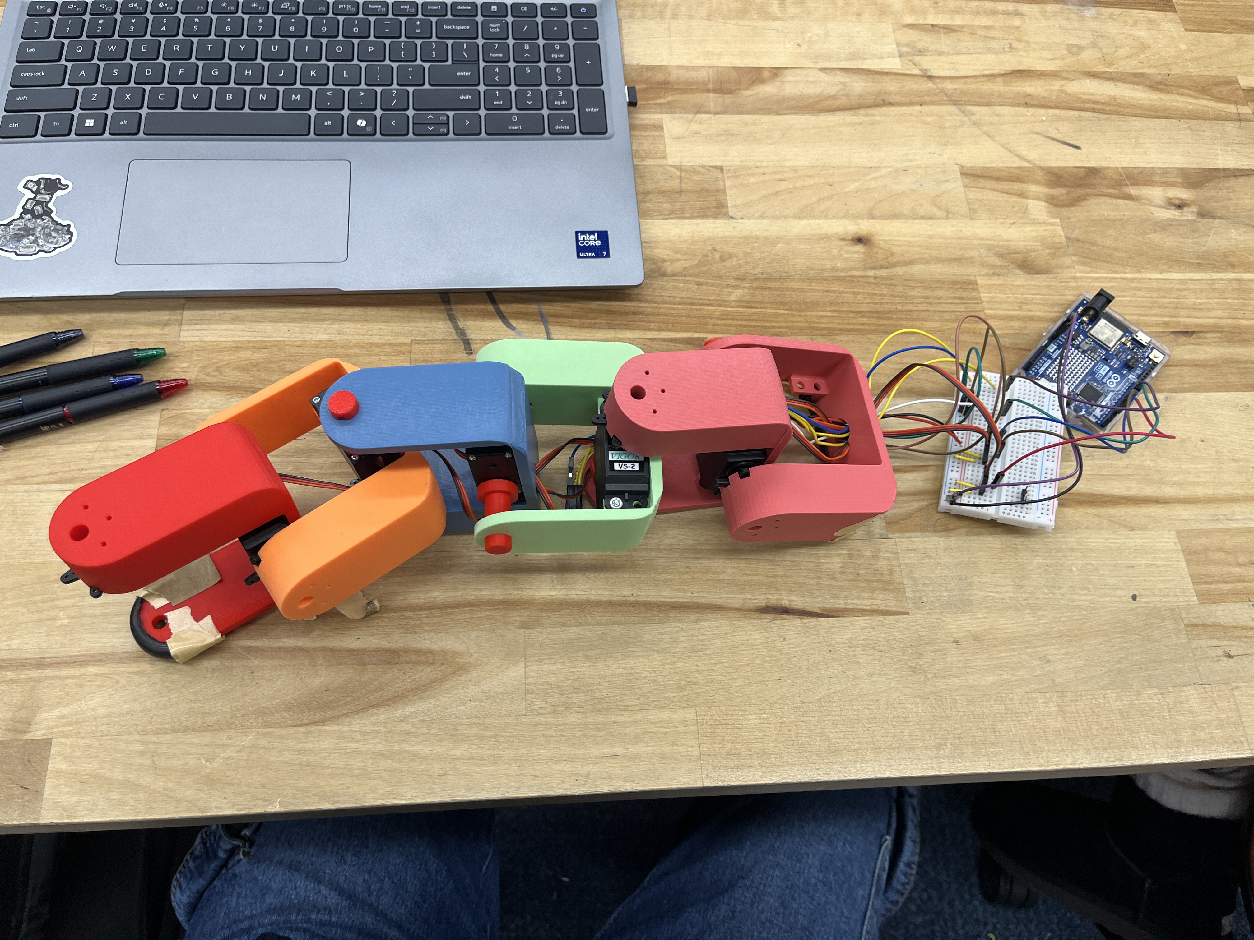
Large image

Servo Motor

We used six servo motors to control the joint motion of the snake. alternated positioning of the servos on each link, so that the snake has both vertical and horizontal range of motion.
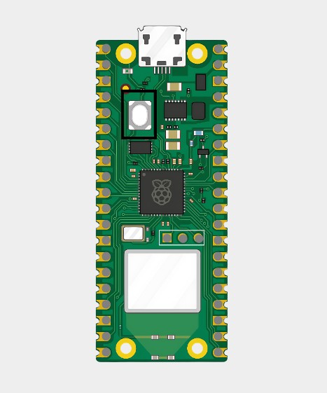
Large image

Raspberry Pi Pico W

We used four Raspberry Pi Pico boards to control the angle of the servo motors and to recieve data from the camera, sensor, and IMUs.

Large image

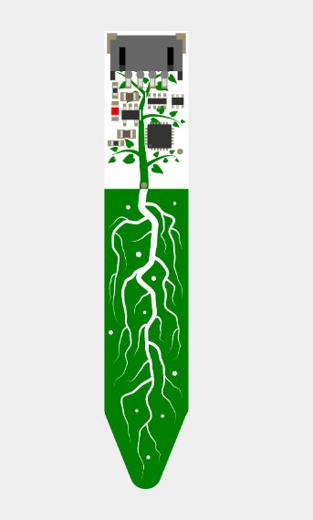
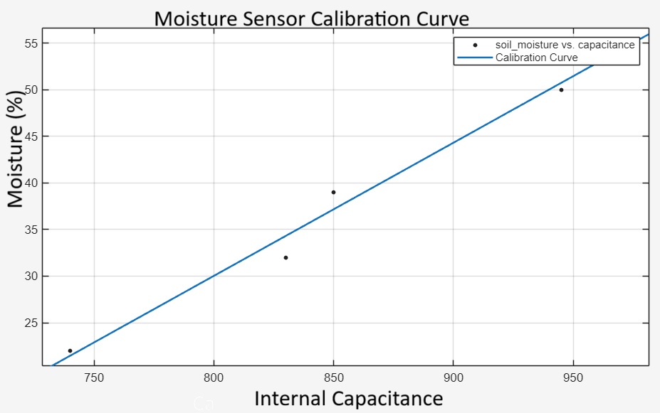
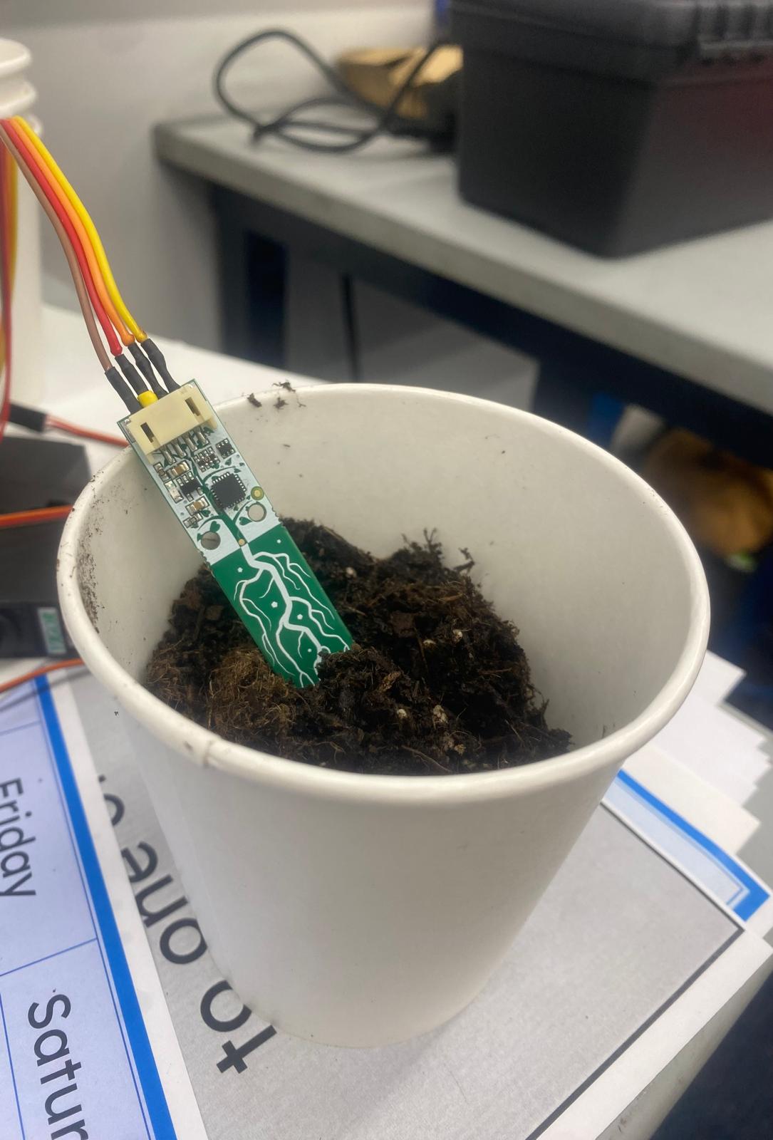
STEMMA Soil Moisture Sensor

We used the Adafruit STEMMA soil moisture sensor to take measurements of soil moisture, based off of capacitance measured.

Large image

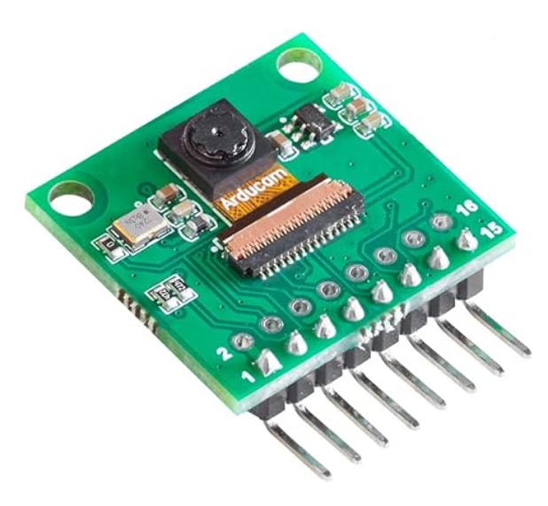
Arducam for Raspberry Pi Pico Camera

We used a camera that connects to our Pico boards to communicate a visual to the user and aids them in controlling the snake.
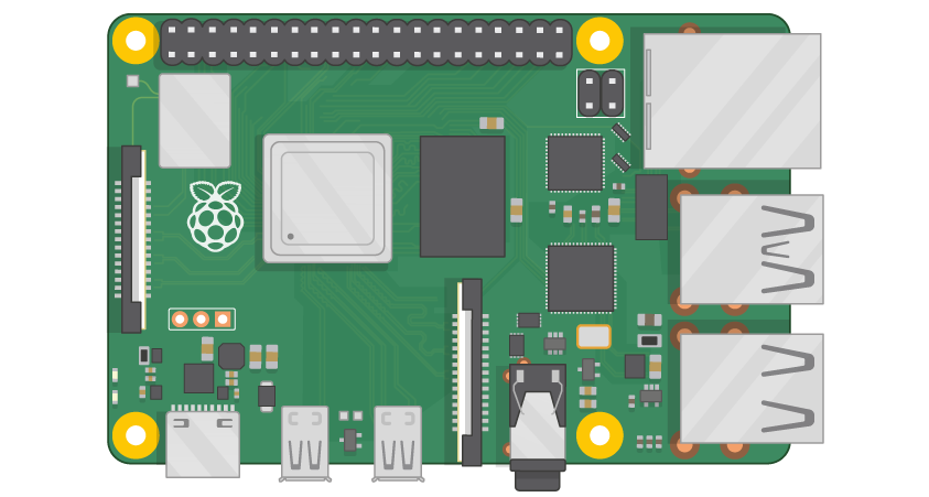
Large image

Raspberry Pi 4

We used a Raspi as a ground station - mostly because we couldn't get our computers to connect to the picos.

Hardware Explanation

We utilized a Raspberry Pi as a ground station to visualize the soil and movement dashboards. The Raspberry Pi communicated with our four Pico W microcontrollers over wifi. Each pico was assigned a different task. One pico controlled the motors, one collected serial data from the soil sensor, one sent serial data back from the camera, and one collected location data from the IMU. Our IMU Pico went unused as we invested the majority of our time on the movement, soil data capturing, and camera vision components.

Wiring

Because the wires had to snake through our snake and move with the joints, we had to be very careful about how we wired everything up. Each servo has 3 wires, for the first sprint, we had them each connect all the way down the snake to the arduino. This was very messy. For the second sprint, we made a wire harness, that allowed us to have one red power wire and one black ground wire that ran through the entire length of the snake and had branches that came off and connected to the servos. However the signal line still ran through the entire snake and made it hard to differentiate which wire was connected to which motor. For our final sprint, we kept the power and ground wire harnesses and braided the signal wires together in groups of 3 with different colors to tell them apart. We also zip tied the original motor wires next to the motor so we didn't have to cut them and they wouldn't be floating around.

Large image

Final sprint wiring. yellow grey and orange braided together.

Large image

First Sprint Wiring

Large image

Wire Harness for second sprint

Large image

Wiring for second sprint

Sensor Calibration

We had an i2c soil moisture sensor that we calibrated using an arduino. Unfortunately, we were unable to get the sensor to read with the picos, so it was not part of our final product.

Large image

Acknowledgements

A special thank you to Oscar Bao for helping us troubleshoot electrical issues.