Phase 1
Introduction
Phase 1 was our initial ideation and testing portion. We came into the project knowing that we wanted to build a helicopter with a swashplateless rotor system, so we started by gaining a basic understanding of this system and then went on to set goals. We primarily worked on initial prototyping, requirements definition, and test rig setup in this phase.
Goals for Sprint 1
1. Order the swashplateless system’s motors and electronics
2. Make a two axis testing rig capable of pivoting in all of our relevant directions
3. Make an initial prototype for our swashplateless's mechanical system
Initial Design and Integration
Mechanical - Testing Rig
Our idea was to have a rig with 2 pivots.
One would allow us to see how our rotor system responded to roll inputs by the controller,
and the second pivot would allow us to see how it responded to pitch inputs.
Our goal was to have two-axis thrust vector control before mounting all of the components on the helicopter.
We started by designing and fabricating the single-axis testing stand. Once everything was mounted correctly,
we could analyze the net thrust vector for the roll inputs. After designing and implementing one-axis control,
we added a second pivot to our testing rig for pitch inputs. Once everything was integrated,
we could test how our rotor system responded to the pitch and roll inputs done by the controller,
and could begin advancing the design of the rotor system.
We knew we wanted to base everything around using 8020 aluminum extrusions,
as they are a very common prototyping material which we had easy access to.
For this first iteration of the testing rig, we only tried to have a single axis of rotation.
.jpeg)
Once we had done some initial ideation, we went on to do press fit testing for the 8020.
We had previously worked with the material, but wanted a better press fit so that we could minimize
wiggle caused by the testing rig– the more solid the connections, the better.
We went through multiple iterations before landing on an effective sizing.
Once we had our pressfit sizing set,
we designed and printed the pivot for the top and the mount for the bottom.
With both, we used our pressfit sizing.
We did our best to minimize filament use and printing
time by using lower infill and removing extraneous material in the parts.
At this point, we had the main portion of the testing rig complete. However, we still needed to work on the upper portion,
where the rotor system would be attached. We used our previous 8020 pressfit testing to create
a piece that would slot into one side, then serve as a pivot for the rest.
.jpeg)
We ended up using wood screws to attach the base to a 2x4, with the intention of clamping the 2x4 to a table or pair of chairs whenever we wanted to test. We discovered a little wiggliness in the various pieces as well, and decided to hold them in with wood screws through the 3D prints–it held securely, didn’t destroy the 80/20, and was quick and easy to mount.
Mechanical - Swashplateless Pivot System
While designing the first version of our rotor system, these were our initial design considerations:
1. It needs a pivot that allows the pitch angle to change with rapid changes in speed
2. It needs to be able to be mounted on a motor
3. Low Friction is a must
4. The rotors need to be the same radius from the center
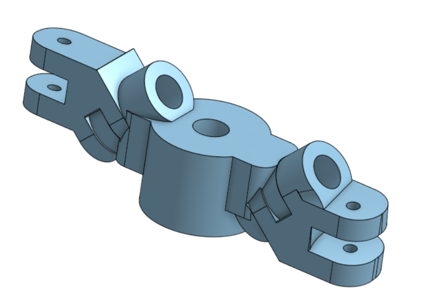
Based on these requirements, we created an initial prototype.
This prototype consisted of a 3D printed hinge in single shear
held together by an underconstrained dowel.
This was just a proof of concept that this design was
sufficient for blade actuation and was not yet integrated with the motor.
Here's a picture of our initial CAD prototype for the Pivot System
Electronics, Firmware, Controls, and Motors
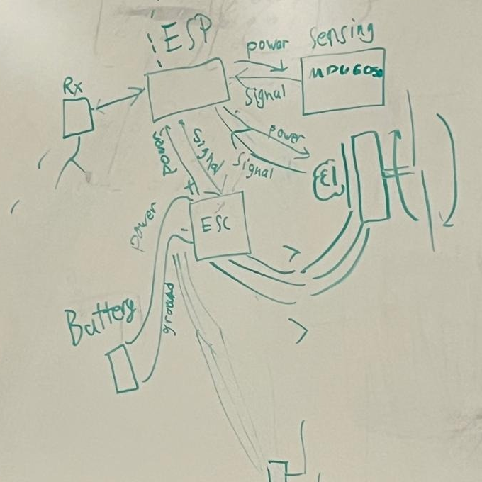
We first drew out an initial draft of our overall system diagram to determine a basic,
birds-eye view of electronics and firmware so we could start ordering parts. The main component decisions we had to make were for the main motor, flight controller, and microcontroller running DSHOT
because they needed to have a sufficient update rate in order for the helicopter to respond to commands and change its thrust vector within a motor rotation.
We decided to go with SunnySky's V4006 high efficiency 380KV motor because it was a relatively inexpensive motor which had a sufficient update rate required to change rotor acceleration throughout rotation.
Optimally, we would've used a Teensy to run DSHOT commands due to faster update rates, higher performance, and it was what was used in the video we referenced our design off of. However, we did not have one at hand at the time, and we were also running out of budget,
so we decided to go with an ESP32 we had on hand in order to immediately start testing. This decision did not appear to affect our performance as ESP32 is able to send DSHOT600 at ~1k Hz which is sufficient enough to control the helicopter for much less of a cost. We also did end up burning
through a few ESP32s... so maybe it's a good thing we went with the cheaper microcontroller.
Decided to go with Flywoo GOKU F722 PRO V2 Flight Controller flight controller for interfacing with iNav.
Ordered all relevant electronics and motors. We’re planning to wait on the tail motor
– we have motors accessible through aero which we can use.
Tail Rotor Calculations
Tail rotor systems are essential for helicopters, they provide a counteracting force
to the aircraft's main propeller torque. Which prevents
the helicopter from turning uncontrollably in the opposite direction of the main motor's rotation.
In order to counteract the force generated by the main propeller,
the tail propeller must be able to provide enough thrust. So we needed to know how powerful our tail motor needed to be.
After building a physics model of the helicopter and analyzing the forces generated by the main rotor,
we reached the following tail motor requirements:
1. Our minimum target KV was at least 1300 RPM/V
2. The motor must be able to sustain 30V of continuous power and 5A of continuous current
3. The thrust force generated by the motor must be of at least 2 Newtons
Here's our derivation for the tail motor requirements: