Phase 3
Final Phase Overview
In this phase, we continued developing our work and achieved both our basic goal of demonstrating two-axis control and our stretch goal of flying the helicopter! We initially ran into a major roadblock when our testing rig broke, but overcame this challenge and went on to achieve two-axis control of our rotor system's thrust vector. We then transitioned our electronics over to our helicopter, did some integration troubleshooting, and flew it.
The Explosion
Much of our initial work during this phase was precipitated by the explosion of our test rig.
After this breakdown of our testing rig, we discussed possible reasons for the failure. Rewatching videos of the failure of the rig, we saw significant vibrations from the rotor system being transferred to the testing rig and causing significant deformation in our 3D printed attachment pieces.
We knew that some vibration was inherent to a swashplateless system; the acceleration and deceleration of our rotor head was what made it work, in theory. However, we seemed to be experiencing far more vibration than made sense.
We realized that a lot of this vibration could be attributed to our rotor system. The center of gravity of our system was off-balance from our center of rotation, causing unnecessary vibration.
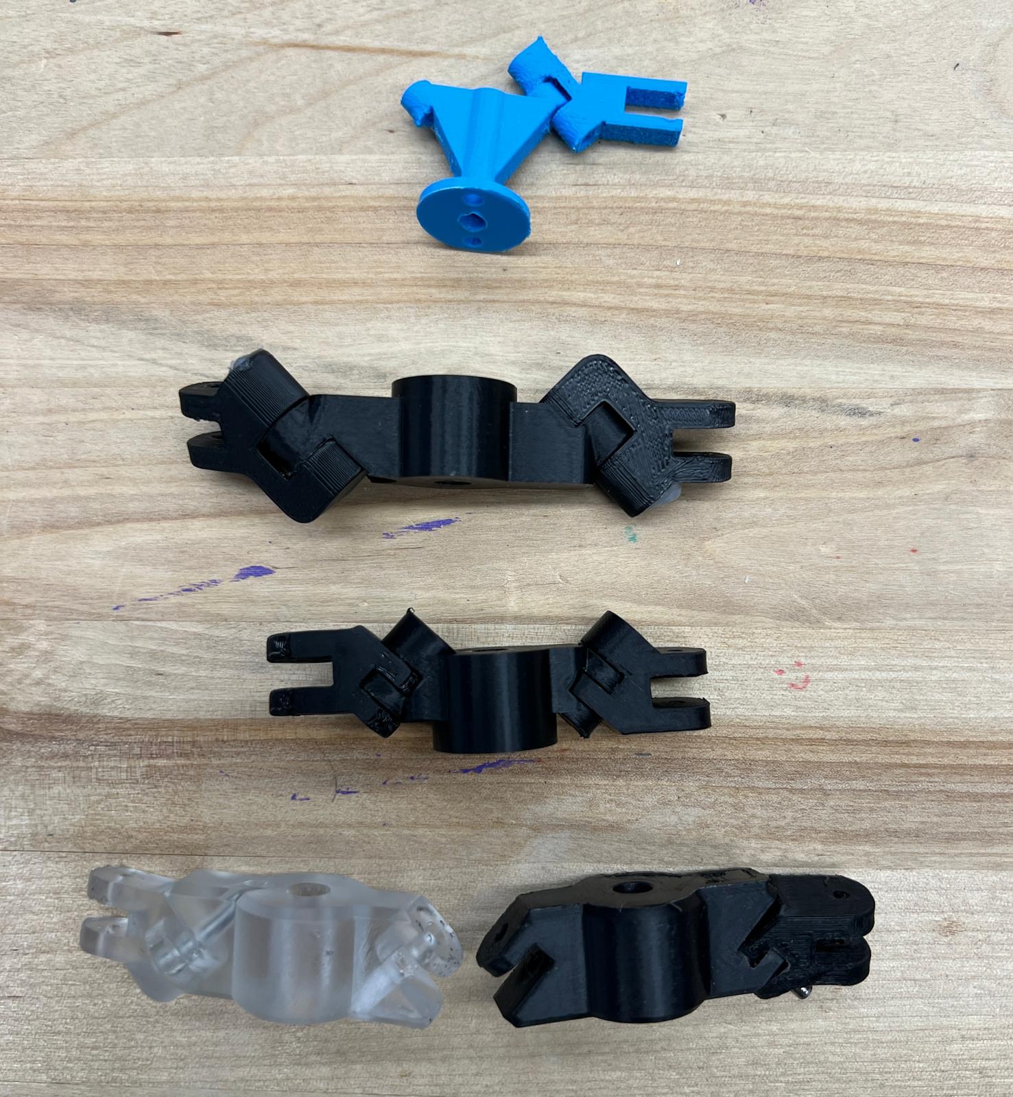
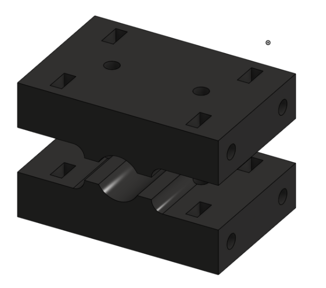
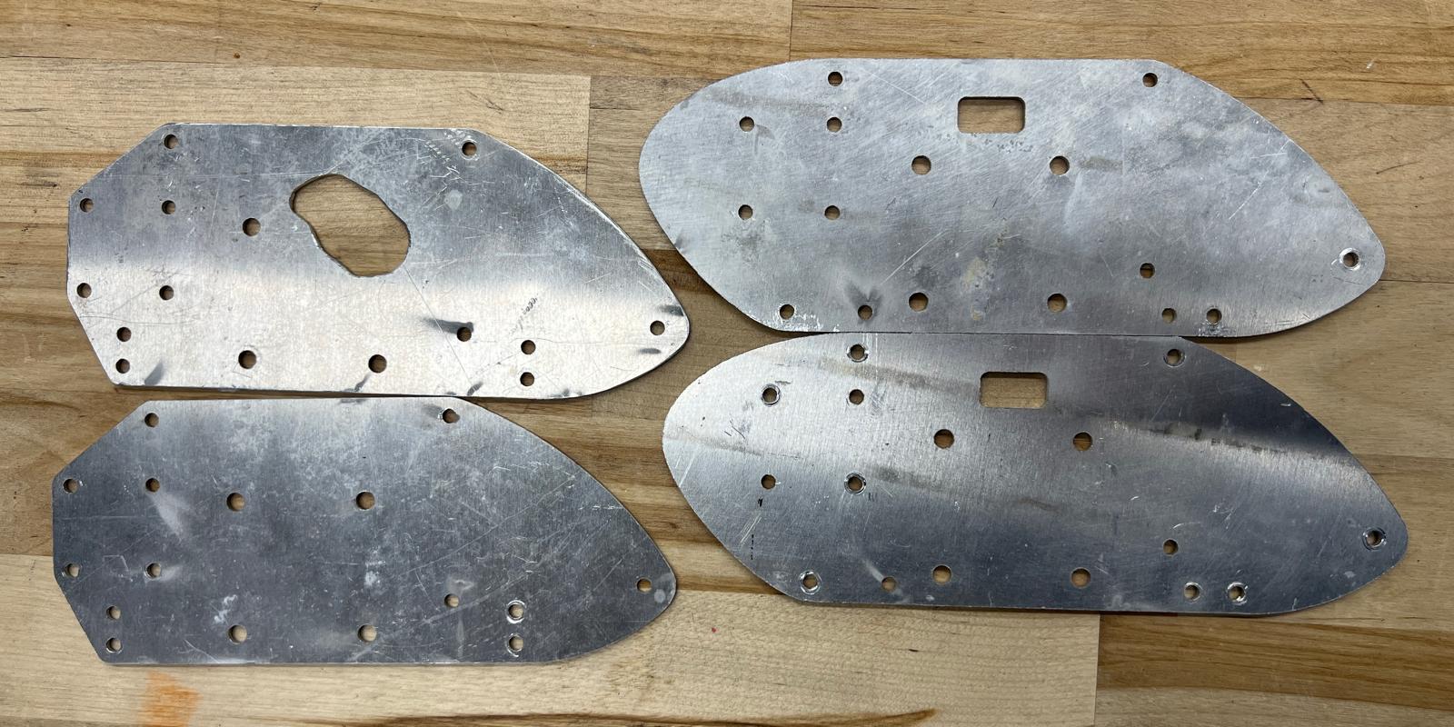
After making this realization, we redesigned the rotor system so that it was perfectly symmetrical, meaning that its center of gravity would be better aligned with the center of rotation (see the bottom rotor systems).
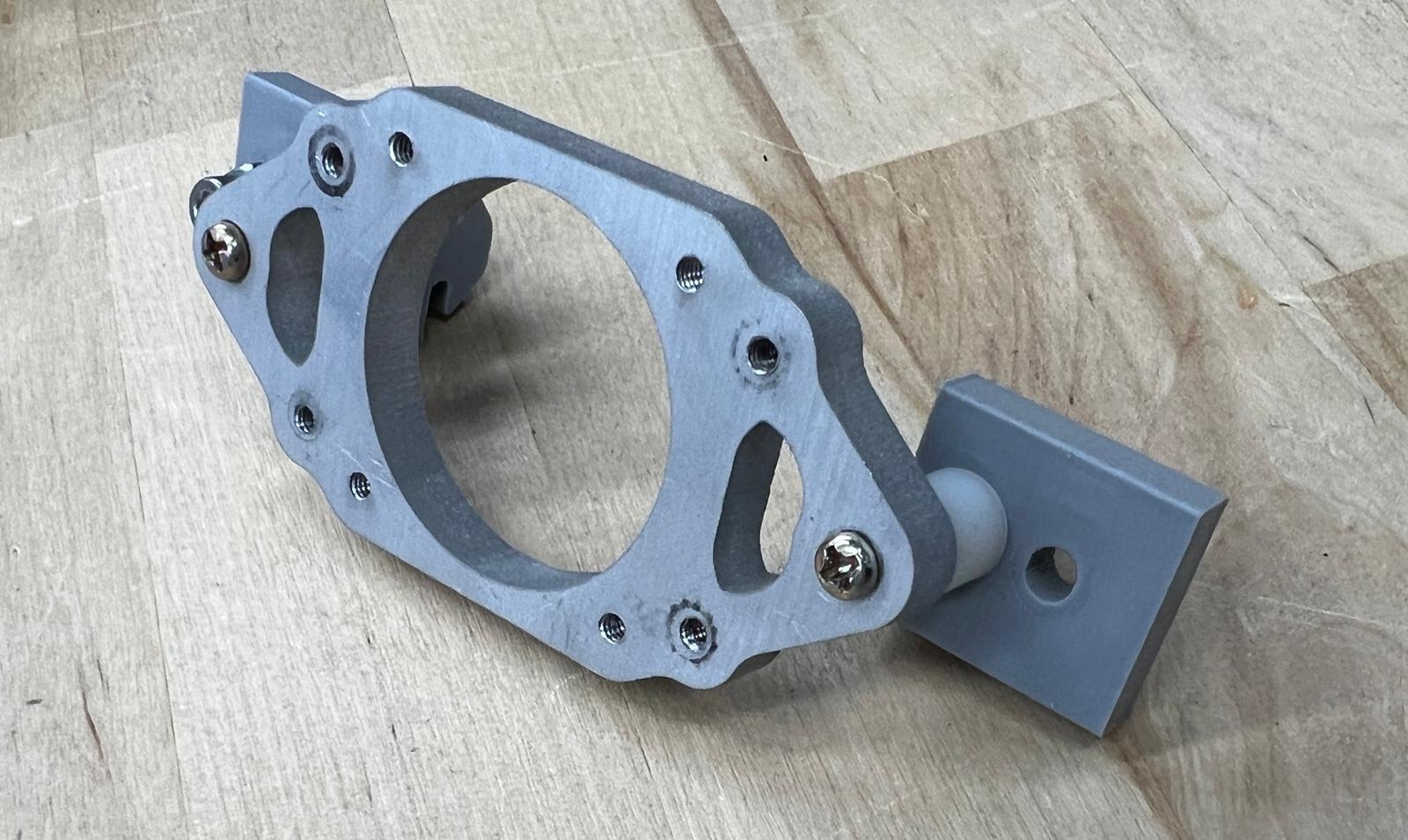
In addition, our discussion of the inherent vibrations that come as part of a swashplateless rotor system helped us realize that we needed to strengthen our testing rig motor mount. We wanted force from the rotor system to be directly transferred to the testing rig so that we could more easily visualize the effects of our testing. For all of these reasons, we cut a new version of a similar, but strengthened, piece out of quarter-inch aluminum plate.
Achieving Two Axis Control
Once we had redesigned our swashplate and strengthened our testing rig, we went back to testing. After some time tuning variables, we fully achieved two-axis control! This was our initial goal for the whole project, so it felt good to achieve.
Helicopter Mechanical Development
Once we had solved our testing rig's mechanical problems after the explosion, we began working on translating our helicopter from CAD into a real mechanical design. Our motivators in this stage were reducing part count and weight while maintaining strength.
With this motivation, we realized that we could integrate our main motor and electronics mount with the crossbars we were using to attach it to the side frame, reducing part count and complexity of assembly.
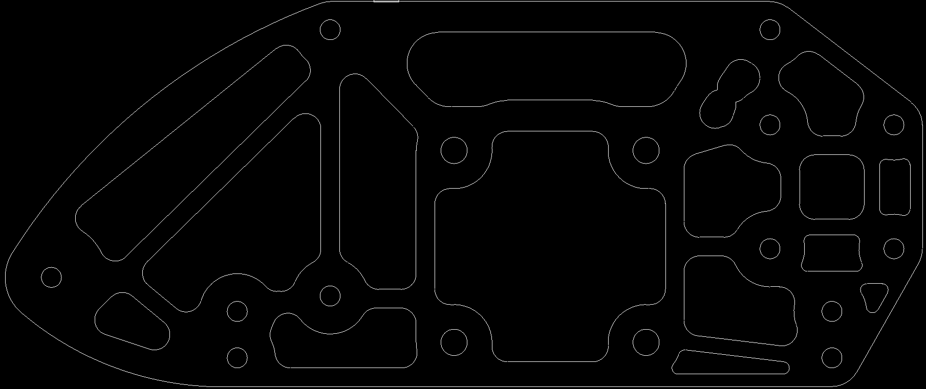
At this point in the process, we also began manufacturing initial prototypes of our helicopter. We waterjetted our side frame pieces out of 16th inch aluminum plate. Initially, we intended to have significant lightweighting in our design. However, when we went to cut it, the shop staff requested that we not cut unnecessary holes, to avoid wasting grommet. For this reason, we removed all lightweighting. Even without it, the pieces still came out very light – 16th inch aluminum isn't very heavy.
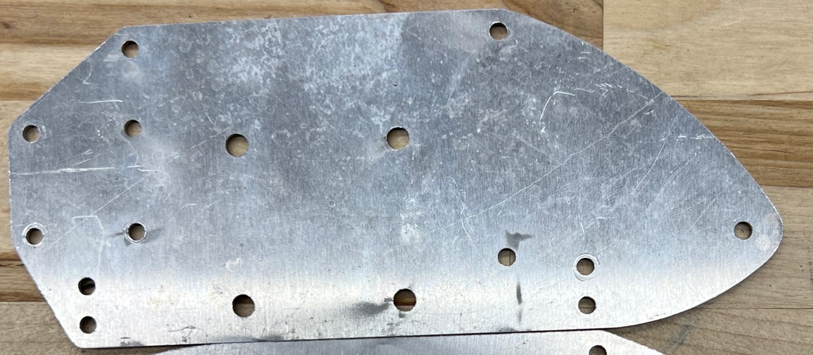
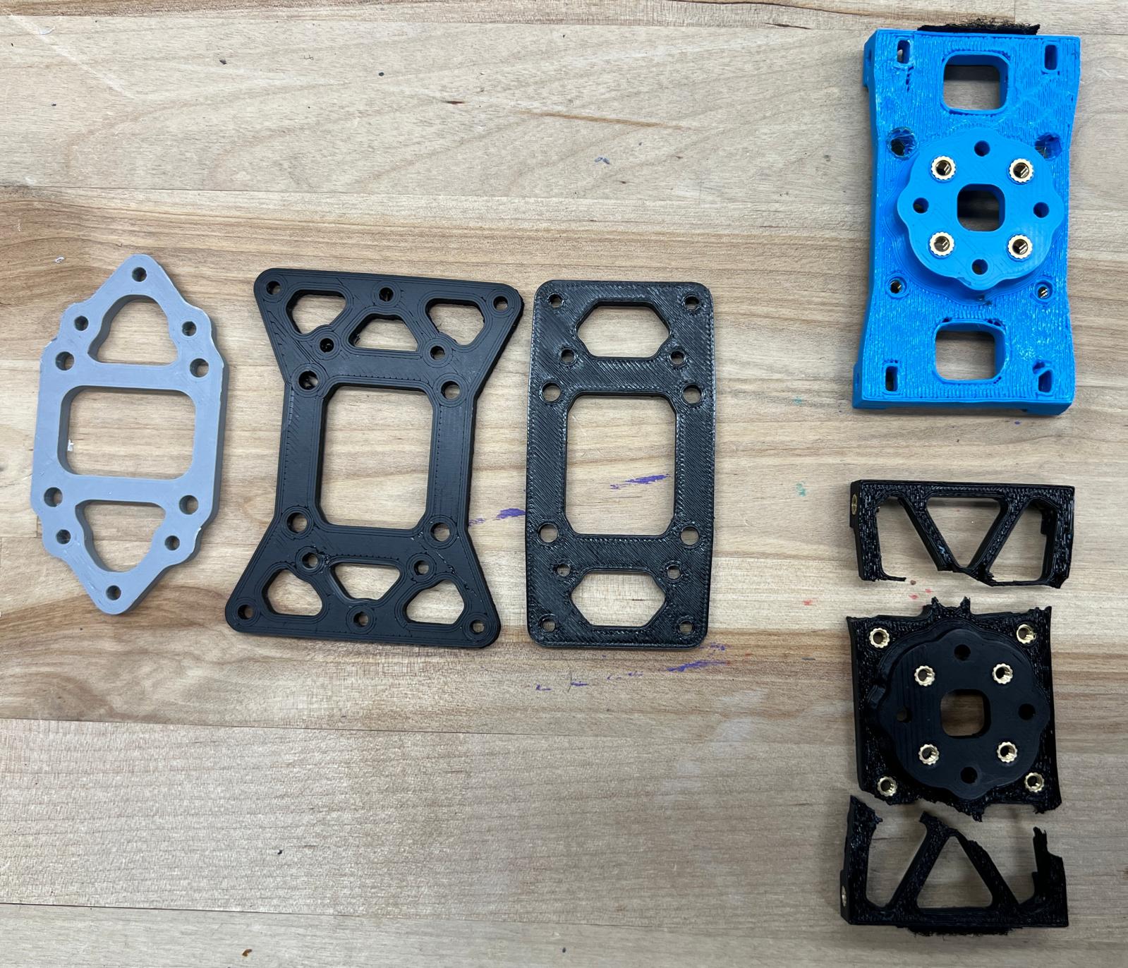
Once we had printed our main plate and waterjetted our side plates, we began putting them together and figuring out sizing. We realized that we could reduce part count further and increase ease of assembly by using heat-set inserts rather than nuts for many connections of our main plate, so we remade the plate to accept heat-set inserts.
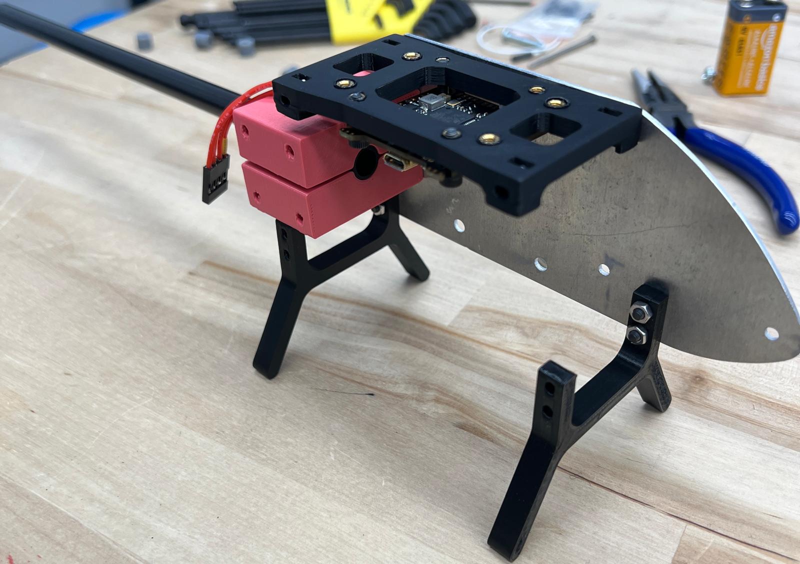
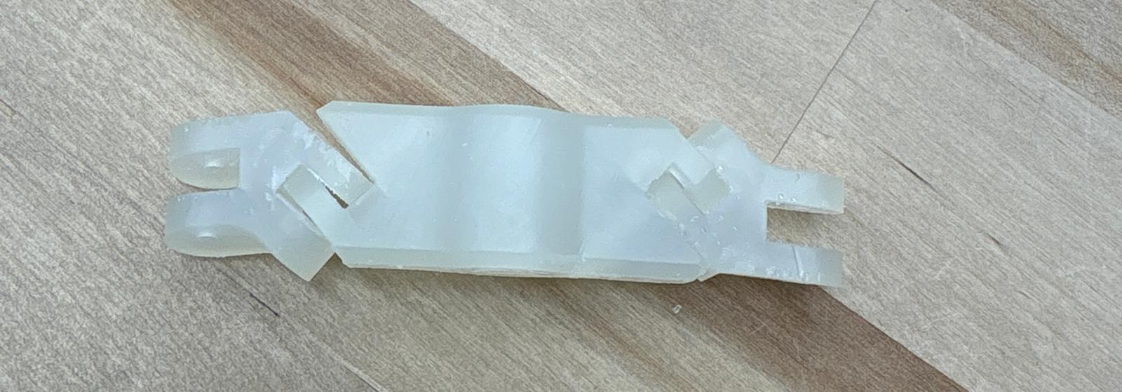
We designed a mount for our tail tube out of 3D printed material, with the same basic considerations; we wanted it to be low-part-count, easy to assemble, and strong. We created a motor tail mount (not pictured) that was essentially a plug glued into the tail rod.
Tail Work
These were our initial design constraints and considerations for our tail and complementary components:
1. The tail must be long enough to offset the tail motor in the right place
2. The tail mounting must be capable of holding the tail and its components, and it must constrain the tail in all directions
3. The tail motor mount has to be strong enough to resist crash impacts, and it has to be able to be dismounted easily
The tail section had 5 major components:
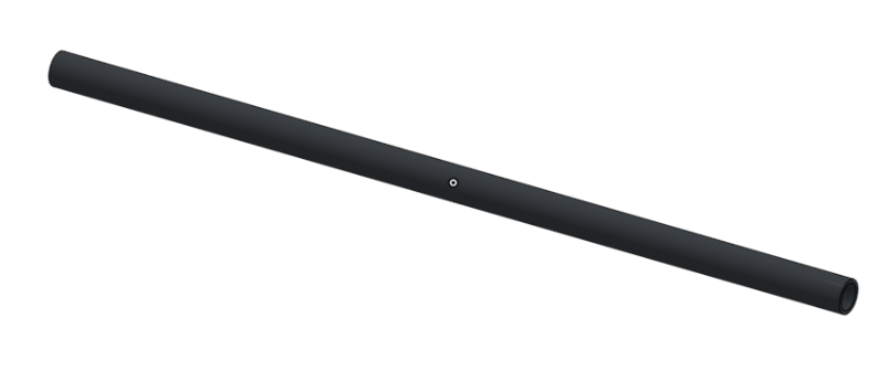
1. Tail shaft: Our tail shaft was a 250 mm carbon fiber shaft with a ten millimeter outer diameter and an eight millimeter inner diameter. It satisfied our physical and aesthetic requirements, so it was a perfect choice.
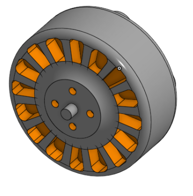
2. Tail motor: The motor we picked was a Diatone Mamba Toka 1505, in the 2650KV version. Our reasoning for choosing this motor can be found here:
3. Tail rotor: We used a 60 mm plastic tail rotor. The blades were big enough that the tail propeller system generated enough counteracting force, and small enough that the blades didn't interfere with the main propeller blades nor hit the ground.

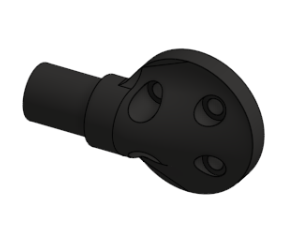
4. Tail shaft mount: We used a set-screw mechanism to clamp the tail to the main body of the helicopter. This design satisfied our requirements of having a strong mounting and easy accessibility.
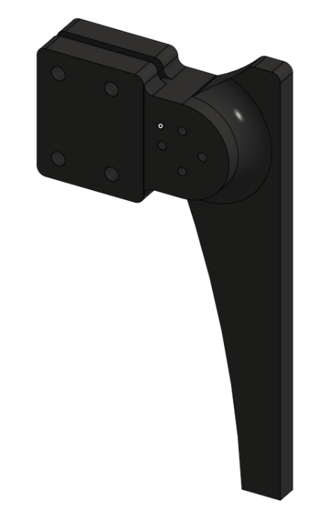
5. Tail motor mount: Our initial design for the tail motor used the same set-screw mechanism as the tail shaft mount, and included supports that aligned with the landing gear for extra stability. However, we decided to pivot to a more minimalistic mount that still met our design goals to reduce the amount of weight in the rear part of the helicopter and balance the aircraft's center of gravity.
Final Sprint to Demo Day
This was the final stretch to achieving our stretch goal: fully integrating the helicopter.
After all of this work on the individual components, we tried putting everything on the helicopter: frame, landing struts, main motor plate, and tail mount, along with all relevant electronics. We knew we needed to do this testing to iron out any kinks we could find.
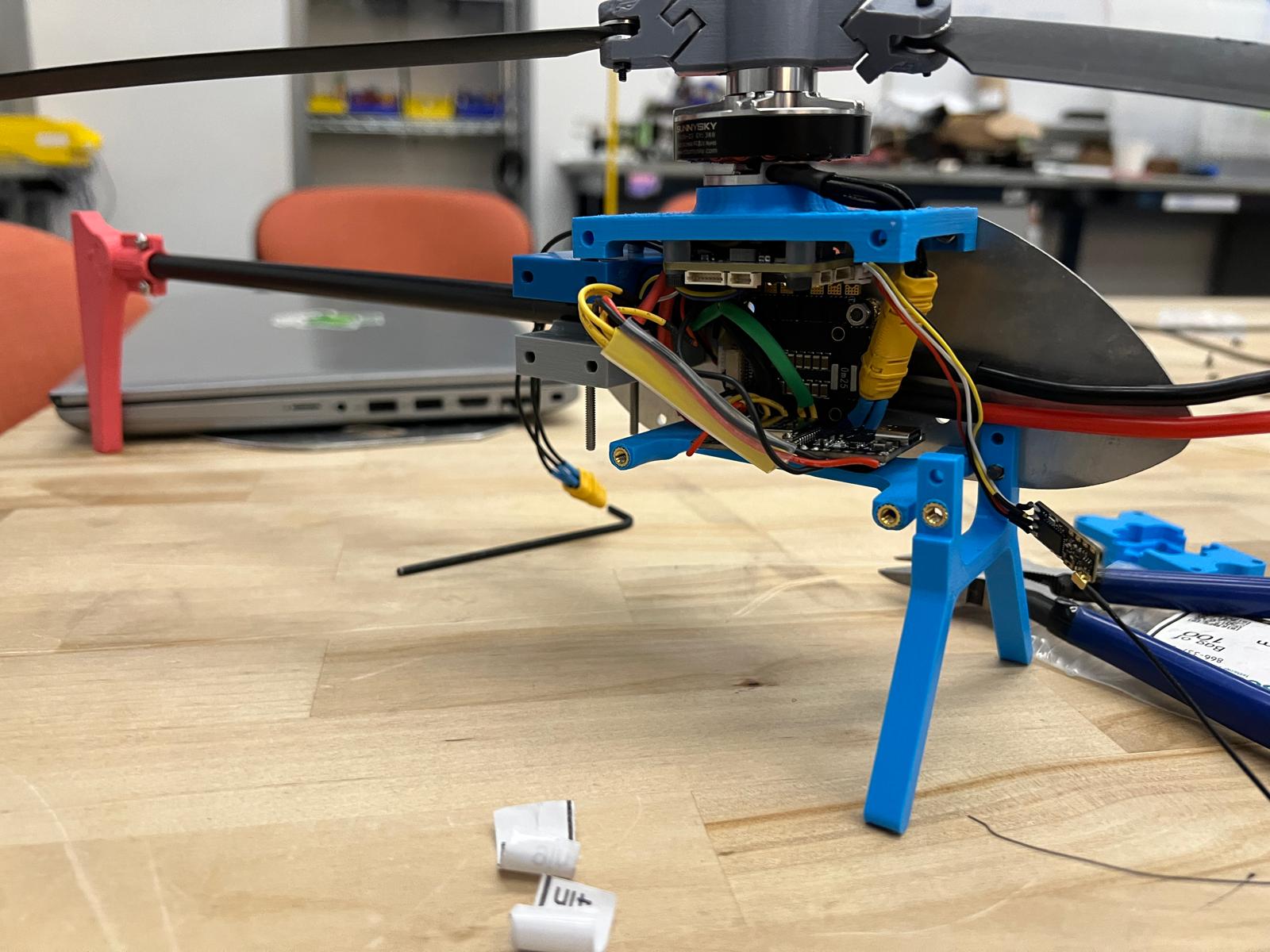
This assembly test had promising results–everything fit! We had enough space for all our electronics, while still having solid attachments for all of our frame components, but there were a few other issues that had to be dealt with.
Testing revealed a problem with our side plate design: we had no way to plug into and update our flight controller, which was mounted on our motor/electronics mount directly below the motor. It was blocked by the side plate.
Our initial fix for this was quick and dirty–we drilled out some holes in the side frame to allow access to the flight controller, but we designed an actual access hole when we ultimately replaced the aluminum side plates with carbon fiber to lightweight the helicopter by ~20 grams.
We finalized the mount design for the electronics and fabricated them using PLA and heat set inserts. We originally wanted to CNC the mount and the struts out of aluminum, but due to time constraints, we settled on sticking with easily manufacturable PLA in order to spend more time testing and tuning the helicopter.
We started having an issue where the rotorhead hinge began seizing up as a result of the PLA deforming when the motor was run at high speeds for too long, so we began experimenting with resin prints for theoretical higher precision, less friction, and durability.
However, we ultimately concluded that resin was too brittle for our uses after the rotorhead essentially exploded due to shear force twice. Furthermore, the resin prints required much more sanding down and fitting than PLA to make sure the tolerances were correct and as frictionless as possible. The benefits of moving from PLA to resin were simply insufficient to warrant longer print times. To fix the issue of the PLA seizing, we added washers inside the hinge to minimize friction between the parts that made up the hinge, which worked.
Testing the Helicopter
We had reached the final stretch! Our helicopter was assembled and mechanically sound. In the days leading up, we had achieved flight with a semblance of control, but had a lot of trouble tuning our control loop.
The helicopter was consistently drifting to the right. We tried both mechanical and software fixes to this challenge–adding more mass to the left side, bumping up our PID values, etc.
Over the course of the night, we did extensive controls tuning–bumping up our proportional and integral constants and doubling the amplitude of the sine wave we used to control the motor. We also tuned our center of gravity, adding an extra aluminum bar in the front of our helicopter. This tuning worked – we were able to obtain controlled, stable flight. We did it.