Phase 2
Phase 2 Overview & Main Goals
This phase was focused on refinement of the progress started in the previous phase.
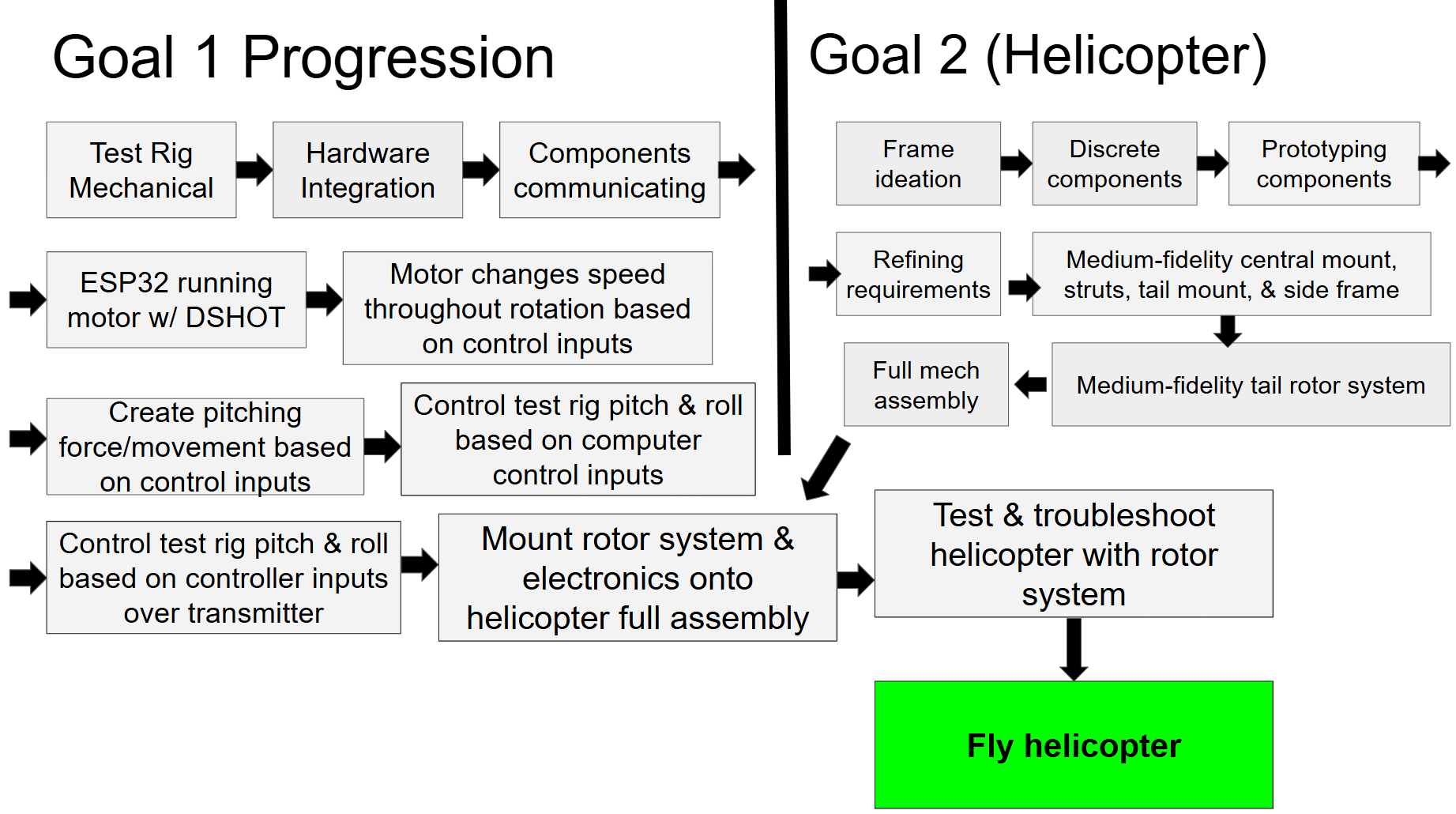
Our main goals for this phase were:
1. Refine our rotor system
2. Add a second axis to our testing rig for pitch control
3. Write an initial version of the controls algorithm for our rotor system
4. Begin testing the rotor system on our rig
Design and Integration Progress
Mechanical - Rotor System
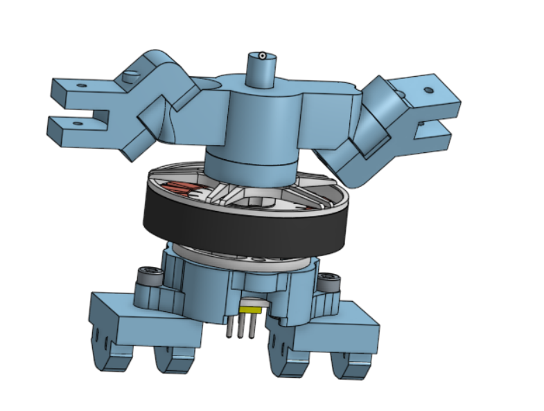
In this phase, we made some improvements to our rotor system.
We had noticed that it was very “wiggly,” being unconstrained
in axes beyond our intended ones. We added additional constraint
by switching from a single to a double shear configuration.
As part of this redesign, we constrained the dowel by using
heat-set inserts with inset screws to hold the dowels in place.
We also implemented a double shear as opposed to a single shear
for a stronger and more stable hinge.
Technically, this introduces more friction,
but this is easily overcome by slightly increasing tolerances.
Finally, we realized that the blades had no initial pitch at
baseline and therefore were not generating any upward thrust.
We redesigned the hinge such that the blade was now held
at a 7 degree angle off the horizontal when the rotor itself
was held straight. In the process of this change,
we also moved the hinge closer to the center of rotation,
reducing the inertia and drag of the rotor system.
Mechanical - Testing Rig
As we transitioned into this phase, we were given a testing cage
by the class teaching team (“The Thunderdome”) to run testing
of our rotor system while maintaining safety.
The attachment point for our testing rig to the Thunderdome
was square aluminum tubing, not 8020. We changed our pivot mount
so that it would fit on this tubing. After initially attempting to
create a perfect pressfit, we decided to instead use screws to
create friction to keep the mount securely on the broader cage.
Once we had figured out this lower mount, we decided to continue
improving the testing rig by adding a second axis of rotation.
Our primary requirement for this second axis was that it could be
easily converted into a one-axis testing system –
we knew we’d want to initially test with one axis, then two,
so an easy transition between the two would be useful.
We made this transition simple by making it so that a pin could be
inserted into the pivots of the first axis of rotation to hold them
in place, making the two-axis rig into a one-axis rig.
Mechanical - Motor, Propeller, and Electronics Mount
While undergoing our testing rig redesign, we also had to create
a means of attaching the motor and rotor system to the testing rig.
Initially, we had a setup in which the motor was connected to
sliders for the 8020 “seesaw” on our testing rig.
At the same time, we were beginning to think about how we would
mount our electronics. Our flight controller, electronic speed
controller (ESC), and ESP32 had all arrived, so we were doing
initial brainstorming on attaching all of them to the helicopter
.jpeg)
We found the CAD for all our electronics, decided on hole patterns,
and printed out initial versions. After creating these initial
patterns, we realized that the same hole pattern could be very
easily used for mounting our motor on our testing rig. So we did.
It worked perfectly.
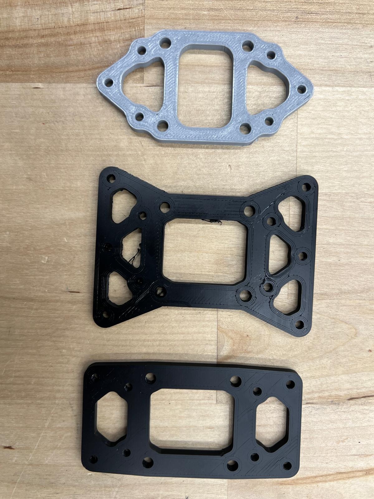
We continued developing this same electronics mount for use on the helicopter, as a main plate where we would mount the flight controller, ESP32, and motor/rotor system. We went through several additional iterations of this system.
Software - Controls Algorithm
We continued developing our firmware and communications protocols. At this stage, the swashplateless rotor system is running off
of serial command from the user on a computer that is physically
connected to the ESP32. The ESP32 is reading the encoder with
I2C, calculating the output, then writing DSHOT commands to the
electronic speed controller (ESC). DSHOT is a racing drone
protocol used for its high speed communicating rate.
The ESP32 is constantly running this loop and writing to the ESC
based on Throttle, Pitch, and Roll commands from the user.
.png)

Integration - Initial Testing On Our Shawshplateless System
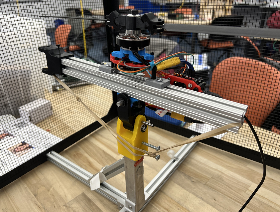
With our motor and electronics mounted onto our testing rig,
and the rig pinned to one-axis mode, we began testing.
We needed to tune the mechanical system and figure out software
issues. With some debugging and other troubleshooting,
we got it to work!
Mechanical - Helicopter Frame Initial Design
When our more mechanically-minded team members weren’t working on
the testing rig, rotor system, or electronics mounting, we spent
time developing our helicopter’s mechanical layout and parts.
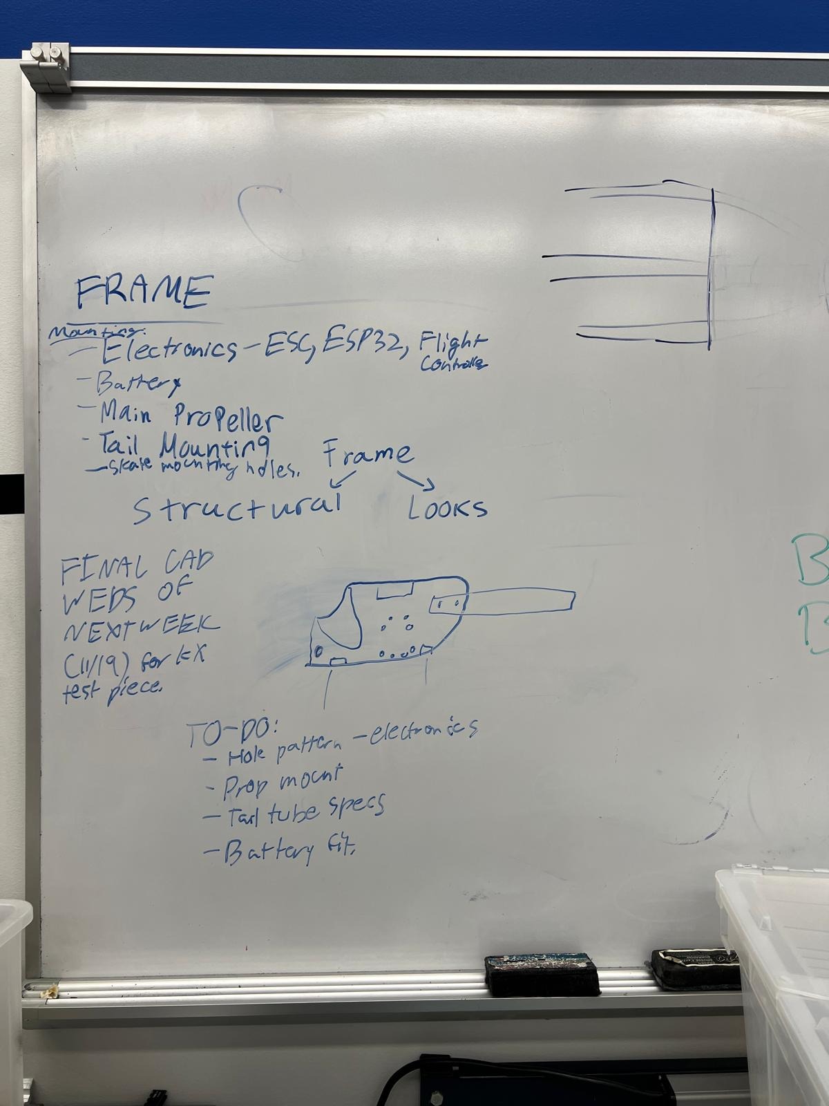
We started by brainstorming the frame.
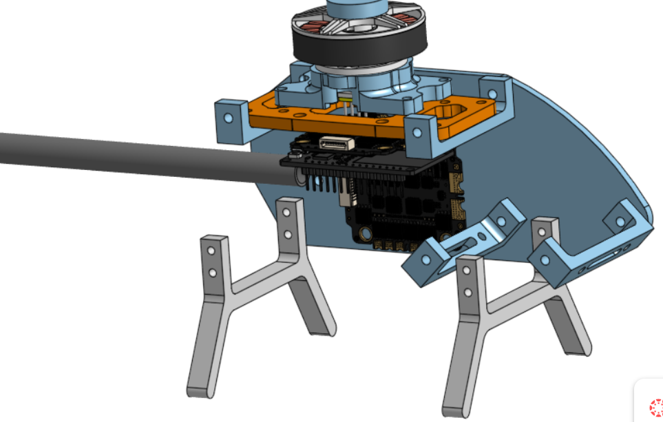
We decided that we wanted a rig based around two side plates
–one on each side. The electronics, motor, and so on would all
be sandwiched between these two plates, with the tail jutting out.
Based on this decision making, we began designing the helicopter.
We designed the side plates to look vaguely helicopter-ish.
The main plate was mounted at the top, the landing struts were
at the bottom, the battery was in the front to balance out weight,
and the tail was in the back. The design was inspired by
Tom Stanton’s swashplateless helicopter.
We planned to waterjet our side plates out of 16th inch
aluminum. Everything else would be 3D printed, besides possibly
a standoff we’d lathe for the very front to hold the battery.
We planned to mount our main electronics/motor/etc plate onto
two crossbars at the top of the frame. Our ESC would be attached
on the side of the frame, and we would use the landing struts as
crossbars.
Recap
We achieved a great deal in this phase! We created a mini-timeline
for our minimum viable product (the two-axis control of thrust
vector on the testing rig). We were doing well on that timeline,
and also making good progress on the helicopter’s mechanical
design, too. Onto the next phase!