Electrical Systems
Circuit Design & Schematics
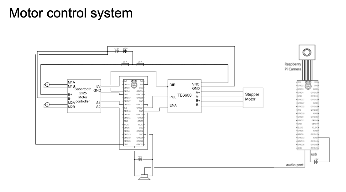
Motor control system
The robot is driven by two high-torque DC motors for the main drivetrain and a stepper motor for the head. The electrical system is powered by two 12V batteries wired in series to create a 24V power supply. To protect the electronics, we used a 20A fuse for the main drive motors and a 30A fuse for the head motor.
The head motor (NEMA 23) is run by a TB6600 stepper driver, while the large drive motors use a Sabertooth 2x25. Both controllers operate in RC mode, receiving PWM signals from the Raspberry Pi on GPIO pins 22, 23, and 24. To ensure a reliable signal, the controllers share a common ground with the Pi but draw logic power from the Pi's 5V rail.
The audio signal is also routed from the Head Pi to the body speakers through a slip ring (measured at 0.20 resistance), allowing for continuous rotation without signal loss. The Raspberry Pi dynamically alters the signal waveforms based on input from the remote controller to manage speed and direction.
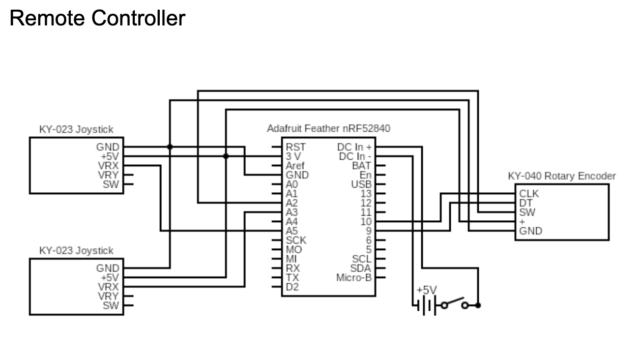
For the Adafruit Feather nRF52840 Express (Remote Controller)
The core of this robotic control system is the Adafruit Feather nRF52840 Express, which serves as the central processing unit and wireless transmitter. The entire circuit operates on a 3.3 V logic level, meaning the microcontroller regulates the power from the external 5 V LiPo battery down to a steady 3.3 volts before distributing it to the sensors. This regulation is critical because it ensures that signal readings remain stable and accurate, even as the battery voltage naturally fluctuates during use.
For the tank-drive movement, the system utilizes two 2-Axis Analog Joysticks powered by the Feather's 3V and GND pins. These joysticks act as potentiometers (voltage dividers). As the user moves the joystick, the internal resistance changes, varying the output voltage between 0V and 3.3V. The Feather's Analog-to-Digital Converter (ADC) reads this changing voltage and translates it into a digital value between 0 and 4095. The Right Joystick connects to Pin A3 to control the right wheel, and the Left Joystick connects to Pin A5 to control the left wheel.
Head control is managed by a KY-040 Rotary Encoder; it generates "On/Off" pulses as the knob is clicked into different positions. It connects to the power rail (3V/GND) and sends these position signals through two data pins: DT (Data) connected to Pin 6 and CLK (Clock) connected to Pin 9. The software monitors the timing difference between these two pins to determine if the rotation is clockwise (CLK pulses before DT) or counter-clockwise (CLK pulses after DT).
The encoder also had an integrated push-button wired to Pin A2, using the Feather's internal pull-up resistors to detect when the knob is pressed (which makes the robot make R2D2 sounds).
Power consumption analysis and battery life estimates
The primary electrical systems are powered by a 25.6V DC bus, made from two 12.8V LiPo batteries wired in series. This high-voltage rail feeds two distinct motor controllers: a Sabertooth 2x25 which drives the main motors, and a TB6600 motor controller which manages the head rotation stepper motor. To protect the circuit, the head motor circuit uses a 20A slow-blow fuse; this stays under the controller's rating while allowing for the brief current spikes without tripping. The main drive circuit is protected by a 30A fuse. While the Sabertooth 2x25 can handle higher currents, the 30A limit was selected based on our operational load analysis. The battery's internal Battery Management System (BMS) acts as a final fail-safe against overcurrent events.
During integration, the system used a DC-DC converter to step the main battery voltage down for the Raspberry Pis. But later on, we discovered that rapid motor braking or direction reversals generated significant voltage spikes (stall currents), causing the Raspberry Pis to reset and drop SSH connections. To resolve this, we completely isolated the logic power by utilizing two independent 5V power banks to provide reliable and safe power to the Raspberry Pis.
This separation of power sources is also a safety feature: an external Emergency Stop (E-Stop) button is wired to physically sever the 25.6V high-power connection, instantly halting all motion. But because the computing cluster is on a separate supply, the Raspberry Pis remain active even when the E-Stop is engaged; preventing corruption that the sudden shutoff could cause, as well as making it easy to access and program while the main power supply is off.
For the main 24V battery pack:
Battery Specification: 2 x 12.8V LiPo in series = 25.6V Total Voltage.
Total Capacity: 15Ah (384 Watt-Hours).
Formula: Run Time (hours) = (Battery Capacity (Ah) × Battery Voltage (V)) / Device Power Consumption (W)
Idle System
Current Draw: 0.5A at 25.6V (Electronics standby).
Calculation: (15Ah * 25.6V) / (25.6V * 0.5A) = 384Wh / 12.8W.
Estimated Runtime: 30 hours.
Maximum Load
Current Draw: 50A (Combined load of 30A drive + 20A head).
Calculation: (15Ah * 25.6V) / (25.6V * 50A) = 384Wh / 1280W.
Estimated Runtime: 0.3 hours (18 minutes).
Nominal Load
Current Draw: 10A (Average driving current).
Calculation: (15Ah * 25.6V) / (25.6V * 10A) = 384Wh / 256W.
Estimated Runtime: 1.5 hours.