System Integration
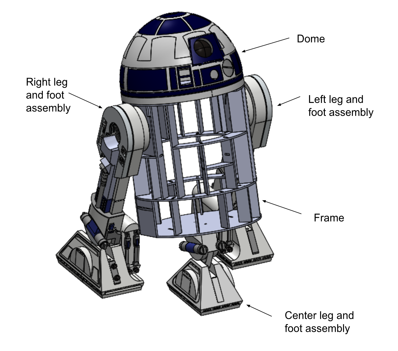
Full CAD Assembly
Code Interaction Flowchart
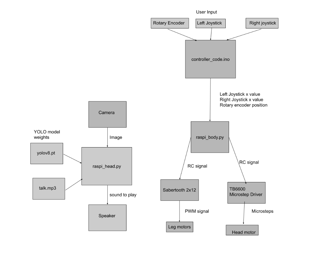
The adafruit feather runs controller_code.ino which receives input from the user operating the remote control and transmits it to the body raspberry pi running raspi_body.py which encodes it as a 3 RC signal for the 3 motors. This is sent to the motor drivers which translate into a PWM signal to control the power sent to the motors.
The camera takes pictures of the world from the point of view of r2d2 and transmits it to the raspberry pi in the head running raspi_head.py. This runs a YOLO inference using yolo8.pt weights to detect objects. If it detects an object it plays talk.mp3 on the speaker.
System Diagram
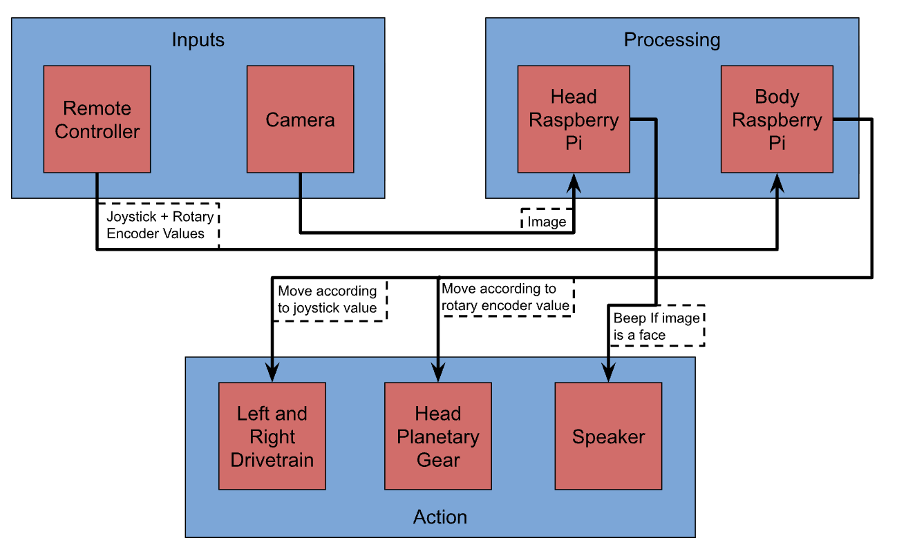
As shown in the subsystem relations diagram above, we designed the system around a "Input-Processing-Action" model. This makes sure that the command signals (from the remote or camera) are distinct from the physical actions (motors and audio). We split tasks between a Raspberry Pi in the body (handling locomotion and audio) and a Raspberry Pi in the head (handling dome rotation and video), which both communicate with the controller to execute commanded movements.
Physical Integration
Physically, fitting these components into the chassis was a challenge of space management, as detailed in the physical integration layout diagram above. We constructed a custom plywood frame to house the heavy 24V batteries and motor controllers at the base for stability (low center of gravity), while mounting the sensitive computing electronics higher up. The slip ring located in the neck allows power and data to pass from the stationary body to the rotating dome, enabling the head to spin 360 degrees without tangling any wires.
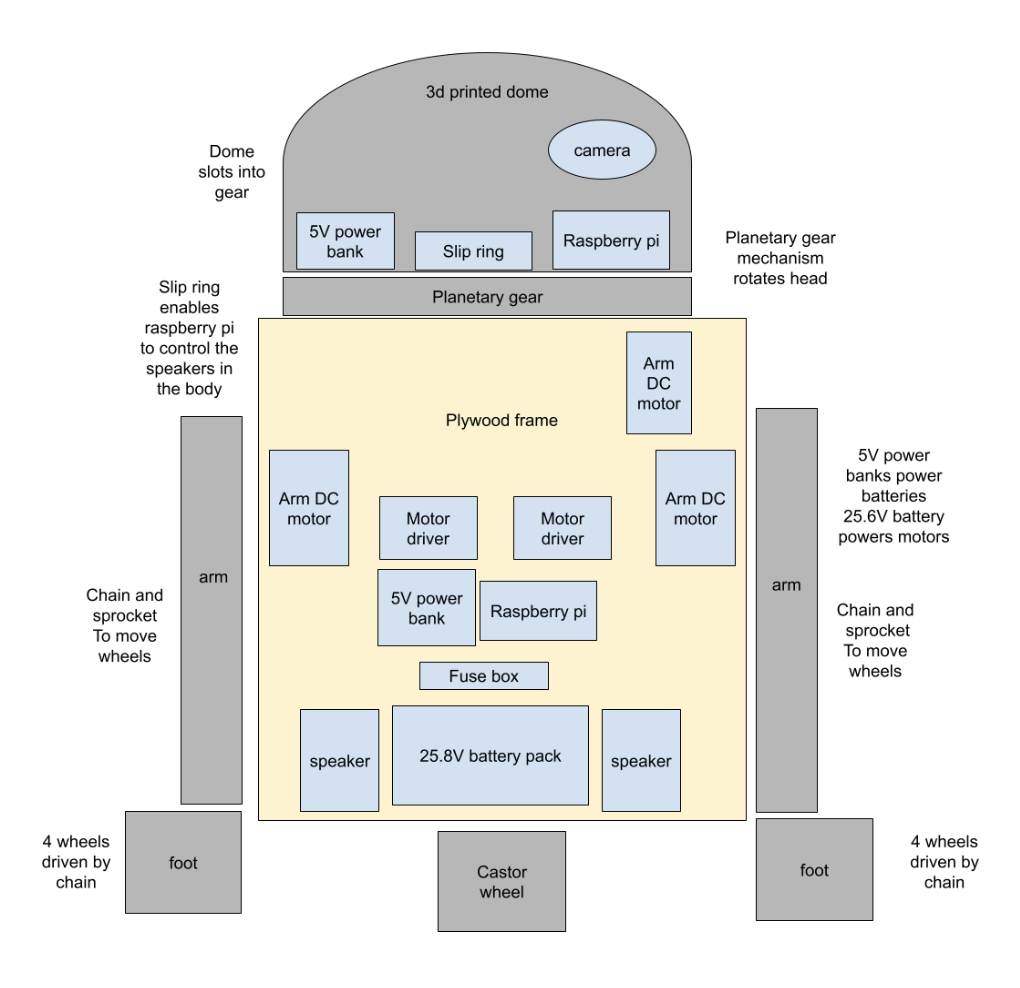
Data & Energy Flow
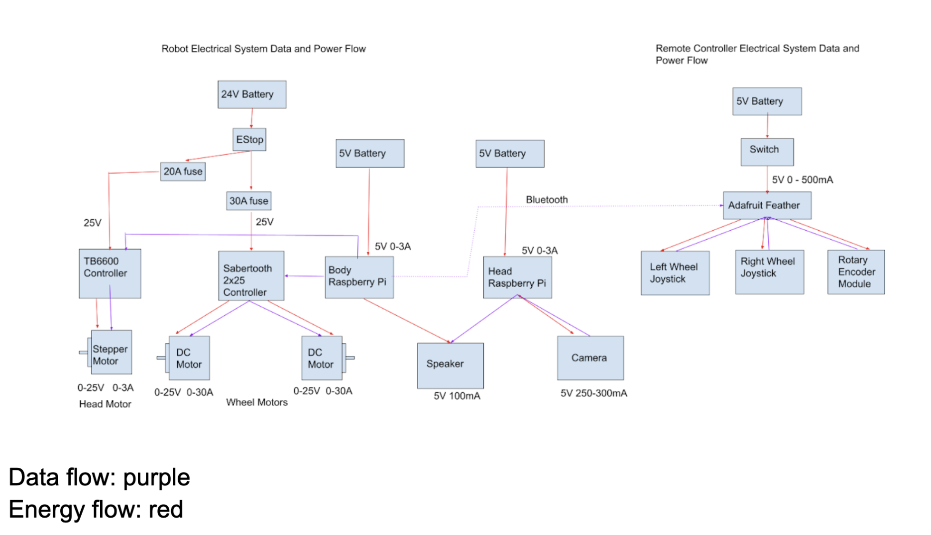
The electrical integration connects the logic to the mechanical power. As seen in the data and energy flow diagram, the system operates on two distinct voltage rails: a high-power 24V circuit for the drivetrain and dome motors, regulated 5V power banks for the Raspberry Pis and sensors, and a 5V battery for the controller.
For safety purposes, we integrated fuses between the batteries and motor controllers (20A and 30A) and included an emergency stop (E-Stop) accessible on the exterior. Data flow is handled primarily through wired GPIO connections for motor control, while the remote controller communicates wirelessly via Bluetooth. This separation of high-voltage power and low-voltage logic was essential to prevent providing excessive voltage (and running excessive current) through sensitive components.
The system uses three microcontrollers, each isolated on its own 5V power supply to ensure stability and redundancy. The control loop begins with the remote controller, which powers and reads data from the joysticks and rotary encoders, transmitting user inputs wirelessly to the body Raspberry Pi. Acting as the central locomotion controller, the body Pi interprets these commands and signals the two motor controllers, which draw from the main 25.6V battery to drive the three DC motors.
The head Raspberry Pi manages more complex computing tasks, including computer vision and audio logic. While the Head Pi controls the audio signal, the physical speakers are powered by the Body Pi, which allows the speakers to remain in the chassis without requiring heavy power cables to pass through the slip ring, while the Head Pi retains the ability to power the camera and process visual data locally.