Mechanical Systems
Design & Fabrication
Note that we heavily modified models that we got online to fit our use: here are the links to the original sources:
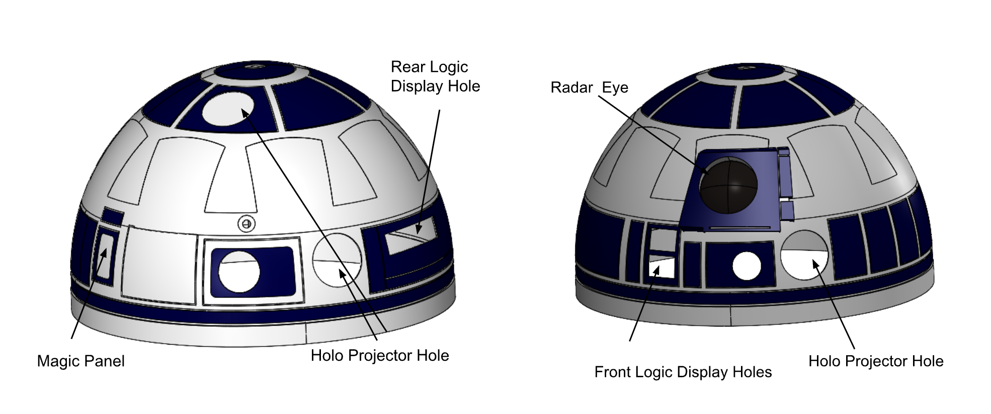
The Dome
The dome is entirely 3D printed as the complicated geometry made that the only option for us due to time and budget constraints. All of the 3D printed parts of the dome itself are printed with PLA. The pegs that attach the dome to the gear system are made out for PETG as they are quite small and we wanted them to be able to hold the full weight of the dome which is approximately 5-10 pounds.
After the parts where printed assembly began and in the Prusa slicer we were able to spit up the dome along the blocks that we added to the Outer main dome so it could be put together with pegs and holes so everything aligned correctly on the first try. We assembled the dome in section first with the top half of it. The outer dome main was put together then the main inner dome was added to make sure the dome was the correct shape before adding any of the outer aesthetic panels. The pieces were all super glued together and the top part of the dome was completed enough to move on the bottom half.
To start the bottom we sanded down the pegs and holes in the outer dome to make sure it fit together with no gaps. Though we did tolerance these pegs in the Prusa slicer, the 3D printers are only so precise. We first glued the bottom section together from the 8 pieces it was in so that it was ready to be put into the top of the dome. The top portion of the dome was also slit into 8 pieces in order to fit on the prusa printers. In total the main outer dome was slit into 16 pieces. Once to the bottom of the outer dome there was glue in place. We put in the inner dome pieces to increase the strength and make sure the dome was the correct shape. The inner dome was in roughly 20 pieces so it could fit on the build plates. After the inner section of the dome was installed we were able to add in all of the aesthetic plates on the outside.
Lastly, we needed to add the borrow ring that goes at the very bottom of the dome to complete the shape and make sure the dome is flat on the bottom. At that point the main portion of the dome was complete and in order to strengthen it we filled all the gaps on the inside surface of the dome with quick dry epoxy.
The last things to add to the dome were the pieces that fill in the holes in the dome. This includes the holo projectors which there are three of. We could not find CAD for these but we found an stl that we could use (included in the dome CAD folder). These are not in the final CAD as there is no way to put an stl into a solidworks assembly properly. In addition to the holo projectors we added both of the Logic displays (glued on) and the radar eye. Which was attached with magnets for easy access to the camera in the eye. The clear portion of the eye is a thin piece of acrylic that was thermo formed to make it in the shape of the lens and be seen through it was then epoxied to the radar eye piece.
The other holes in the dome were covered with flat pieces of PLA from the back as we did not have time to integrate a light up function in those places like there is in the movie. The very last thing was the glue on the pegs in their correct position and then epoxying them in place for the slot mechanism on the gear so the head could be put on the robot but still be removable. At this point the dome was completed and ready to go on the robot.
- Holo Projector STL: Source
- Rear Logic Display Plate STL: Source
- Logic Display Holders STL: Source
- Front Logic Display Plate STL: Source
- Terminology for Dome Source: Source
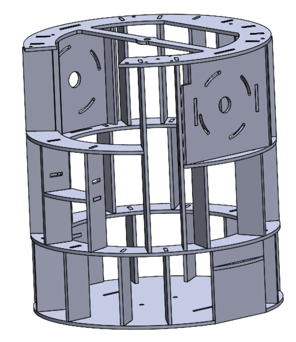
Frame
The frame is constructed from 1/4 inch plywood and features strategically placed holes that reduce weight while maintaining structural strength and support. These openings also provide space for the 3D-printed shell details.
Legs & Drivetrain
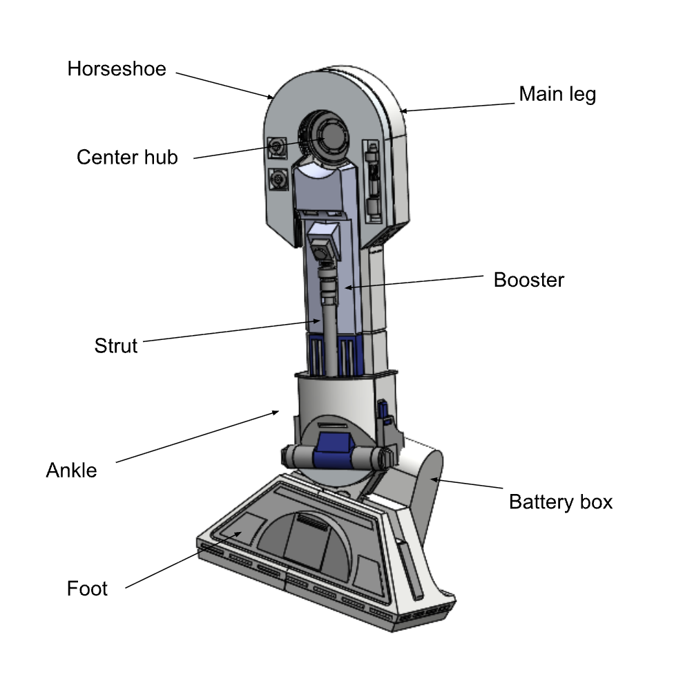
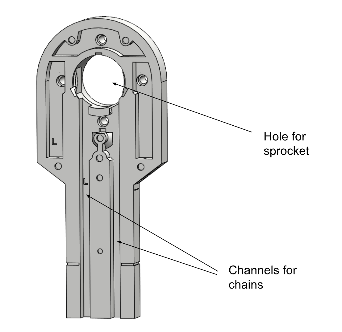
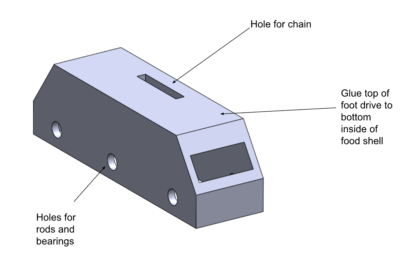
The two side legs are made of PLA and consist of four main parts. The top of the leg includes a standoff that prevents the leg from rubbing against the body. The main leg section contains the internal channels that guide the chain. The ankle section includes holes that allow the chain to pass through, as well as a peg connection for attaching the foot. Finally, the foot assembly consists of the foot shell, an angled wedge that ensures the robot consistently sits at the correct angle, and the drive box.
The drivetrain consists of two main components: a drive box located in the foot of the robot and a sprocket connected to the primary motors mounted in the shoulders of the frame. A chain runs from the shoulder-mounted sprocket, through channels integrated into the robot's legs, and into a central sprocket within the drive box. This central sprocket drives two additional sprockets inside the box, which in turn rotate two axles connected to the wheels, enabling the robot to move.
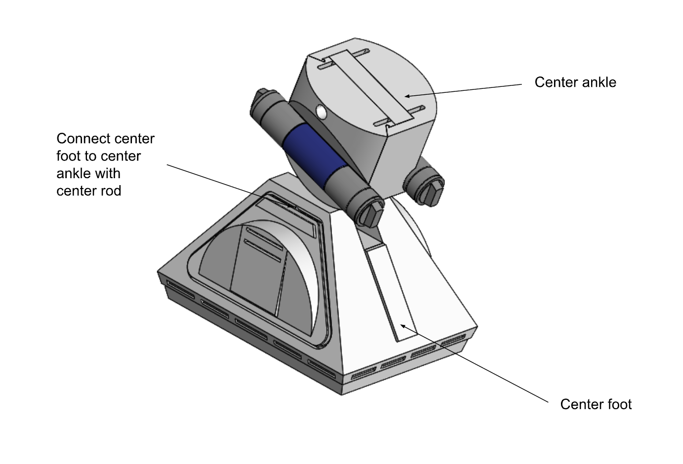
The center foot is also made of PLA and primarily provides support and guidance as the robot moves. No power is supplied to this foot; instead, it rolls alongside the two driven feet using two casters that are evenly spaced inside the foot shell. The foot connects to the main body through a symmetrical ankle that attaches to the foot with a peg, allowing the foot to freely spin and adjust to maintain stability. The ankle is then secured to the body using superglue and two bolts for additional strength.
Head Mechanism
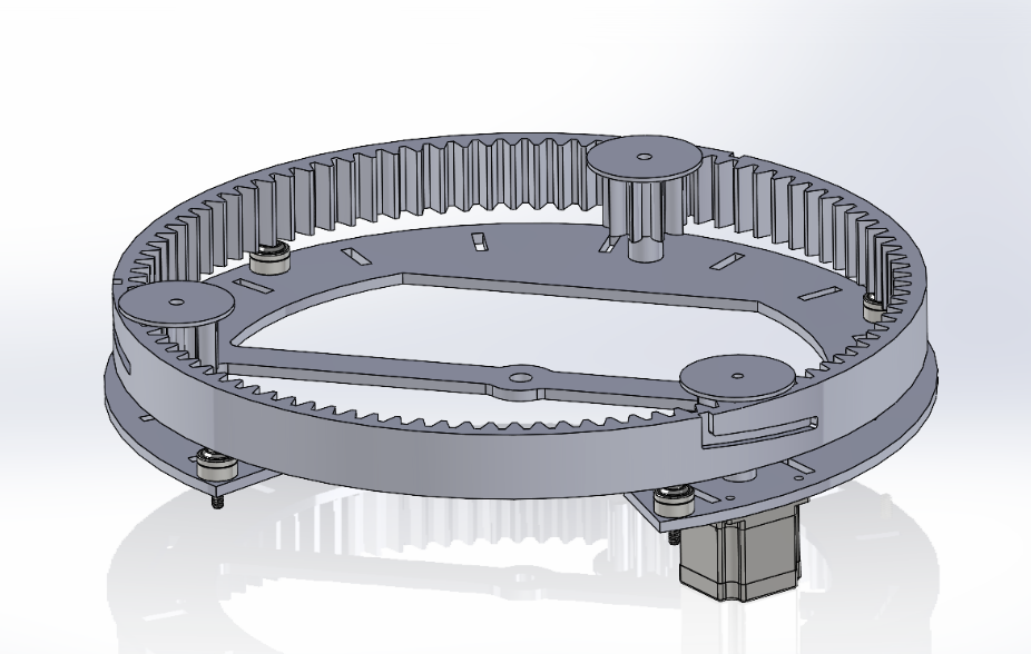
There are 3 main components to the head mechanism: The motor mount, The ring/pinion gear system for rotating the head, and the mechanism that holds the head in place while allowing it to be removed for maintenance. The system is driven by a NEMA 23 stepper motor mounted on the underside of the top part of the frame. The motor drives a 10-tooth gear that interfaces with a hollow 99-tooth ring gear. This gear is held in place axially by two other 10-tooth idler gears spaced equidistantally with the driving gear, as well as by 4 ball transfers keeping it constrained vertically while still allowing it to rotate. 3 slots are cut into the outside of the ring, which interface with pins attached to the inside of the head, holding it in place. To remove the head, it first must be twisted, then lifted straight up. This two-part motion ensures that the head should not come off during normal operation, but is still serviceable when necessary.
Mechanical Analysis
Throughout the design process, we made several critical engineering decisions to ensure stability and durability. Below is a summary of the analysis driving our weight, material, and motor choices:
Weight Distribution & Stability
The R2-D2 unit is tall and prone to tipping if top-heavy. To mitigate this, we performed a weight distribution analysis and prioritized placing the heaviest components—specifically the 24V battery packs (approx. 5 lbs each) and the steel motor drivers—at the very bottom of the chassis. The custom plywood frame was designed with this "low center of gravity" requirement in mind. The lighter components, such as the 3D printed dome and Raspberry Pis, are mounted at the top. This configuration ensures the robot remains stable even during sudden stops or turns.
Material Selection Analysis
We selected materials based on the specific stress requirements of each subsystem:
- Frame (1/4" Plywood): Chosen for its high strength-to-weight ratio and ease of laser cutting. It provides a rigid backbone without adding unnecessary mass.
- Dome Pegs (PETG): While the cosmetic dome is PLA, the structural pegs holding it to the chassis are printed in PETG. Our stress analysis indicated that PLA might snap under the shear force of the 5-10 lb dome rotating, whereas PETG offers the necessary flexibility and impact resistance.
- Gears (PLA): The planetary gear system is printed in PLA. Since the head rotation speed is low and the load is distributed across multiple planetary gears, the yield strength of PLA is sufficient for this application.
Motor Selection Sizing
For the drivetrain, we selected high-torque DC motors capable of moving the robot's estimated 40 lb total weight. We calculated that we needed significant torque to overcome the friction of the carpet and the inertia of the system, leading us to choose 24V brushed motors paired with a 30A-capable Sabertooth driver. For the head, a NEMA 23 Stepper was chosen over a DC motor because we required precise position control (verified by the encoder) rather than just raw speed.