Firmware
Firmware and code for M-O. Check out our Git Repo to view the full source code!
Overall Firmware Architecture
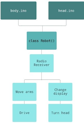
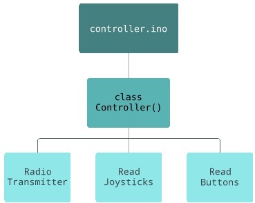
We created an Arduino library, Mo_Lib, to hold all of our code. This library contained two
main classes: Robot and Controller. These hold all of the variables and functions for the
robot and controller respectively. The robot class contains functions for receiving radio
messages as well as functions for controlling both the body and head of the robot. The
controller class contains functions for reading the input from the joystick and buttons then
sending this info via radio to the robot.
Movement
Driving
The code for driving based on joystick input is split between a few functions. The
first,.readStick(), gets the X and Y values of the driving joystick. These are then sent
via
radio from the controller to the robot, where they are passed into a function
calcMotorSpeeds() that converts the joystick value into a speed for each of the motors to
drive at, which can be positive or negative based on the direction. Finally,
setMotorSpeeds() tells the four motors to drive at the calculated speeds.
Head
The code for moving the head is split between a few functions. It reads data from the right
joystick in the controller and sends it via the same method that the drivebase motion is
sent.
However, instead of affecting the speed of the head - which is a relatively top heavy object
- the X input to the joystick's direction is taken and the head is moved in that direction
for the duration that the joystick sends input in that direction. This is done by calling
the step_left() and step_right() functions depending on the joystick reading.
Arm
The movement of the arm functions in a similar way to that of the head; however, the input
data from the controller is different. As opposed to a joystick, the arm’s movement is
controlled by two buttons - one to move it down and one to move it up. Data from all six
buttons on the robot are sent as a bitstring and the first two of these represent whether
the “arm up” and the “arm down” buttons are being pressed.
Based on the direction, the arm movement is then completed by calling the same functions as
the head to step the arm, with it moving up/down as opposed to left/right.
Face
LED Matrix
The LED matrix is used to represent M-O's face and displays his various different
expressions.
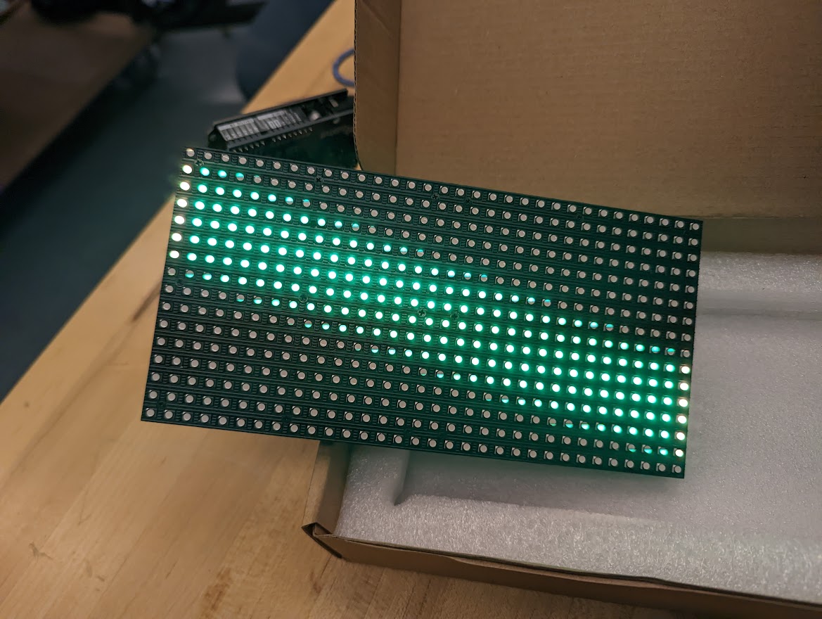
When initially exploring what to use for M-O's face panel, we looked at various types of Neopixel and LED screens where we found that either the price, quality, or size were not suitable to what we wanted. Some of the criteria we were looking for included the following:
- Colored LEDs (at least yellow)
- Quality similar to that of M-O in the movie -
- Large enough to distinctly see the eyes make different expressions
- One single element
- Can be wired to Arduino with enough remaining pins for radio chip data
Based on this criteria, we settled on a 16x32 pixel LED Matrix with the RGB Matrix Shield
from Adafruit.
We started by coding the following functions to display basic expressions on the RGB Matrix:
- blank_eyes() - clears the screen by setting all the pixels to off
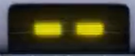
- default_eyes() - M-O's default open eyes
- big_eyes() - M-O's eyes when widened
- closed_eyes() - M-O blinking
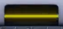
- horiz_line() - M-O horizontal line glitch
- angry_eyes() - Angled eyes that appear mad
All of the expressions were based off clips from the movie itself:
Since we wanted to make two animations for M-O - one happy and one angry - we wrote two
functions happy_animation() and angry_animation() that cycle through some of the expressions
at varying rates.
Finally, we connected the radio chip to the matrix shield and used inputs from the controller
to call the various expressions and animations.